Bearing and gear interfaces reviewed
- Related bores and shoulders
- Functional datums and run-out needs
- Machining and measurement setup
- Assembly method and fit requirements


Control the interfaces that hold moving components in alignment
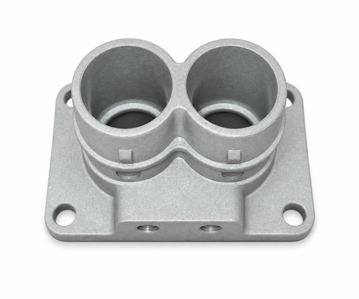
01 · Engineering support
Tool housings support components that rotate, transmit load and generate heat. Identify the bearing seats, locating features and mounting faces that control their relationship before fixing the machining process. The required fit needs to be considered alongside the geometrical accuracy of the seat and its shoulder. Agree how those characteristics will be measured and how the relevant features will be held during machining. The result is an inspection plan connected to the tool assembly, rather than a collection of unrelated hole diameters on a report.
Discuss your requirements
02 · Engineering support
A lighter housing still needs to support its assembly through the intended operating conditions. Review ribs, mounting bosses, fillets and wall transitions as one structure instead of reducing wall thickness uniformly. Casting considerations and the locations of highly loaded regions should be discussed before tooling, with the validation requirements supplied by your engineering team. Drop, vibration and durability results belong to a defined part or tool configuration. Manufacturing decisions can support that validation plan, while the final performance decision remains tied to the agreed test conditions.
Discuss your requirements
03 · Engineering support
A threaded hole is part of a joint that includes the fastener, material, engagement length and assembly method. Bring the tightening requirement and expected service or disassembly conditions into the review. Where an insert or a different thread strategy is considered, assess its installation and inspection requirements with the housing geometry. The drawing and check plan should distinguish thread conformity from any agreed torque or pull-out validation. That distinction helps your assembly team understand what has been verified and what still needs confirmation in the finished tool.
Discuss your requirementsReview bearing relationships, structural support and fastening as parts of the completed tool. Define operating load, temperature and validation conditions before fixing the manufacturing route.
Support related rotating-component interfaces within a housing.
Review: Bore fit · shoulder geometry · datum relationships
Explore this part family
Carry loads between mounted components and fixing points.
Review: Ribs and fillets · boss support · duty-cycle validation
Explore this part family
Position mating components and establish axial contact faces.
Review: Concentric features · face geometry · fastening requirements
Explore this part familyRepresentative component illustrations. Final geometry, alloy, finish and acceptance criteria are reviewed against your drawing and application.
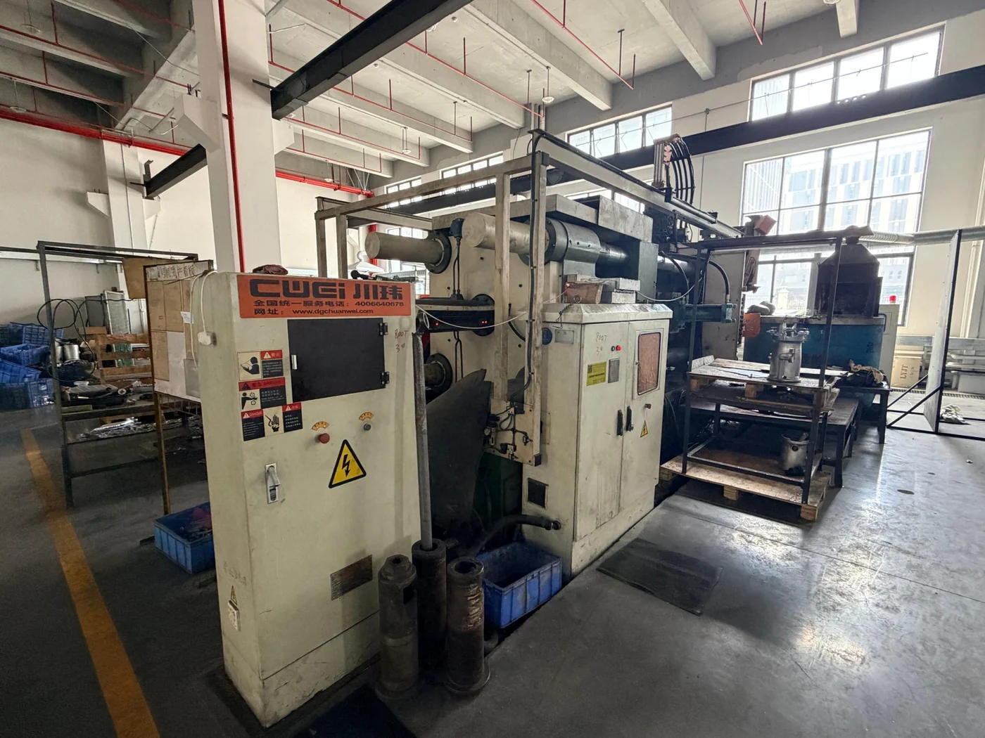
Coordinate the casting and secondary operations around the part you need to receive. The drawing, operating requirements and final delivery condition guide the manufacturing route.
Review tooling, critical interfaces, surface requirements and inspection before production.
Get in touchAluminum is a candidate for many gear cases and structural housings. Zinc may suit detailed smaller components where load, temperature and mass allow. Compare material, rib geometry, finishing and machining against the intended validation plan.
| Material or route | Typical consideration | Confirm for your project |
|---|---|---|
| Aluminum die casting | Housings, structural features and thermal components | Alloy grade, functional geometry, temperature and secondary machining |
| Zinc die casting | Compact detailed parts and suitable decorative applications | Mass, sustained load, service temperature and finish compatibility |
| Machined interfaces | Holes, mounting faces, threads and sealing features | Datums, tolerances, surface condition and measurement method |
| Surface finishing | Appearance and environmental protection | Approved sample, coating-free areas, final fit and applicable tests |

Review appearance samples, preparation, masking and the surfaces that must retain a functional fit. Define the relevant test conditions and acceptance criteria with the part requirements.
Review material and finish requirementsConnect each project requirement to the manufacturing step and evidence needed to confirm it.
Identify the functional features and agree how they will be checked against the drawing.
Keep the requirements and approved references available at the relevant project stage.
Review the operation and setup around the interfaces that affect your assembly.
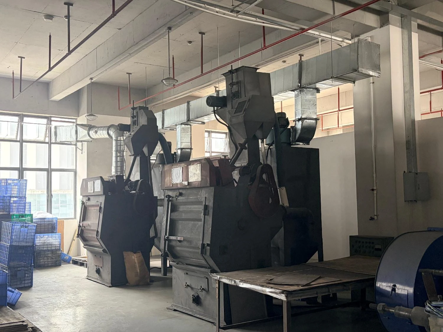
Define what must be protected, finished or checked in the final delivered condition.
Confirm the part, sample or assembly inputs required for the agreed verification.
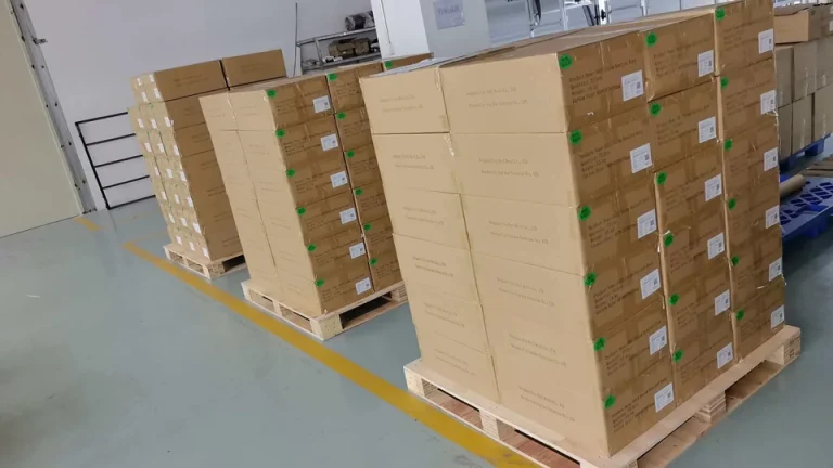
Match handling and packing to the geometry, surface and next assembly operation.
The inspection scope, records and delivery requirements are agreed for the specific part and its intended use.