The complete heat path is considered
- LED board and interface material
- Contact area and mounting faces
- Heat-sink geometry and alloy
- Orientation and ambient conditions


Review the housing as part of the luminaire’s thermal and sealing system
01 · Engineering support
A luminaire housing is one part of the route that carries heat from the LED into the surrounding air. Review the LED board, interface material, mounting contact and heat sink geometry together with the installation orientation. Identify the contact surfaces that require controlled flatness or machining, and confirm the operating power and ambient conditions for validation. More metal or more fins does not automatically remove the limiting interface. The useful evidence is a defined assembly and temperature measurement arrangement that can be repeated when the sample or production design changes.
Discuss your requirements
02 · Engineering support
A sealed light combines the casting, cover, gasket, fasteners and cable entries. Review the groove, mating face and tightening conditions as part of that complete interface, including the effect of any machining or finishing. The protection target should identify the assembled configuration to be tested and the acceptance criteria that apply to it. Changes to a gasket, connector or cover can require further confirmation even if the housing drawing is unchanged. This makes the manufacturing check plan relevant to the outdoor protection expected from the finished luminaire.
Discuss your requirements
03 · Engineering support
The outer finish, mounting bracket and packaging all influence how the luminaire reaches installation. Define the exposure conditions, appearance reference and surfaces that must remain suitable for assembly. Review coating coverage at edges and mounting features, together with the dimensions checked after finishing. If corrosion testing is specified, retain the actual finish system and sample conditions in the report. At delivery, separate visible surfaces and protect projecting features. These details connect the accepted sample to the part your installation team receives, without making an unsupported claim about the complete lamp lifetime.
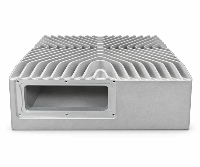
Discuss your requirementsConnect the luminaire housing, thermal body and driver enclosure to the complete light assembly. Review LED contact, sealing and outdoor exposure using the intended installed configuration.

Combine the lighting body, mounting features and heat-transfer geometry.
Review: LED contact areas · mounting points · surface protection
Explore this part family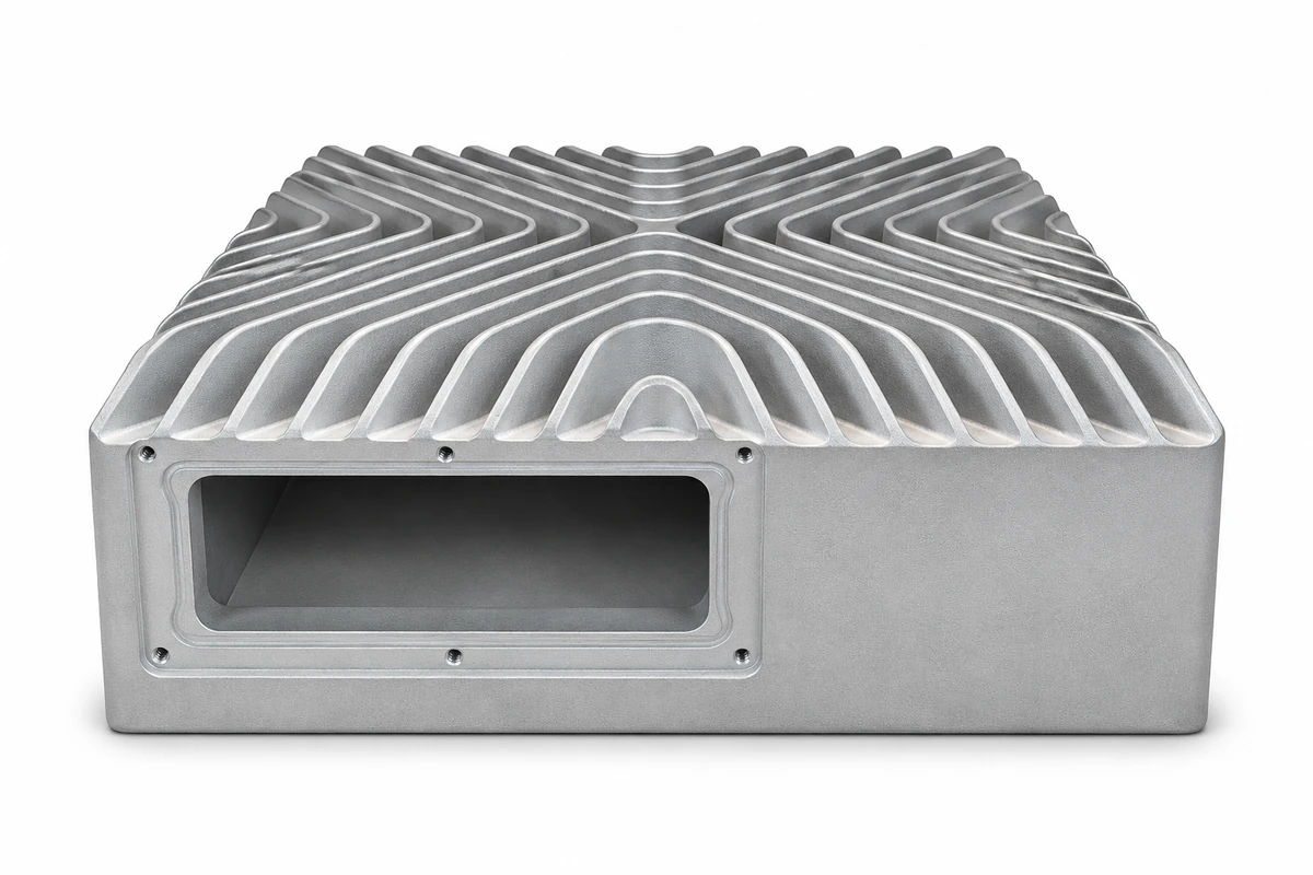
Transfer heat through the specified mounting and contact arrangement.
Review: Base flatness · fin geometry · operating orientation
Explore this part family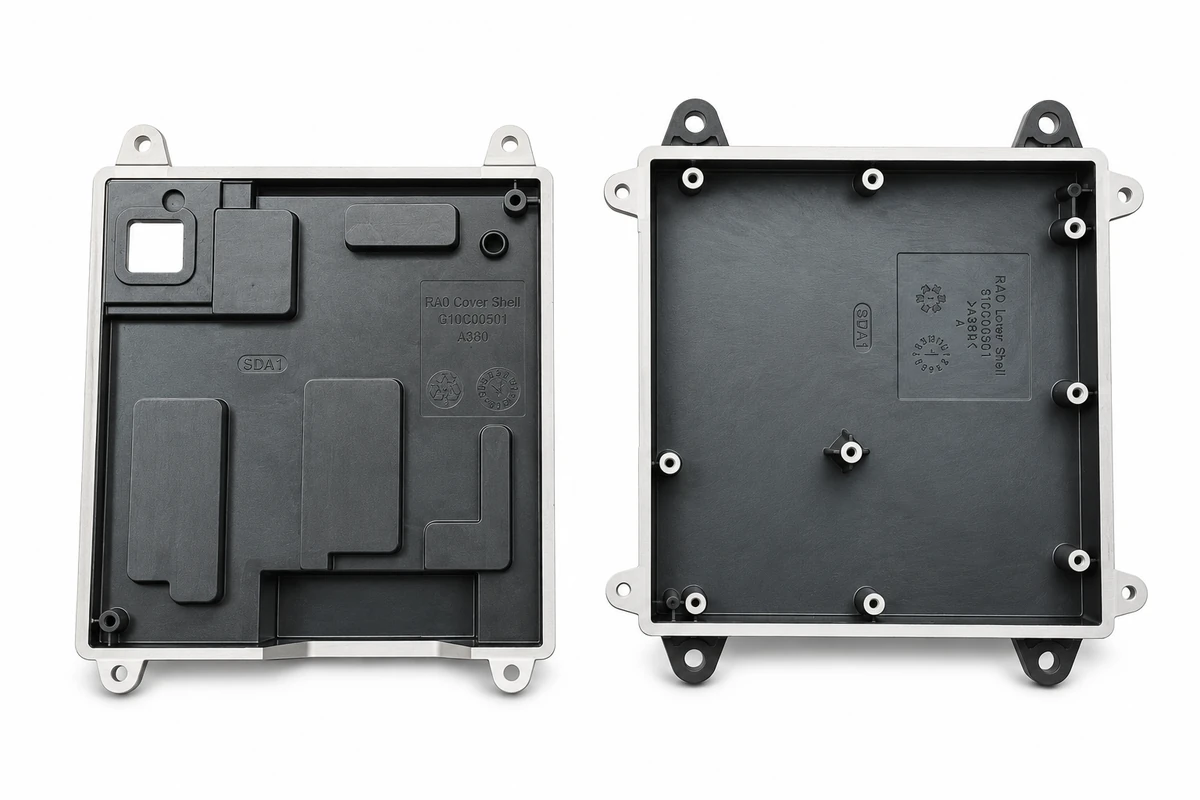
Provide a defined cover and connection interface for the driver or controls.
Review: Gasket interfaces · cable entries · final assembly verification
Explore this part familyRepresentative component illustrations. Final geometry, alloy, finish and acceptance criteria are reviewed against your drawing and application.
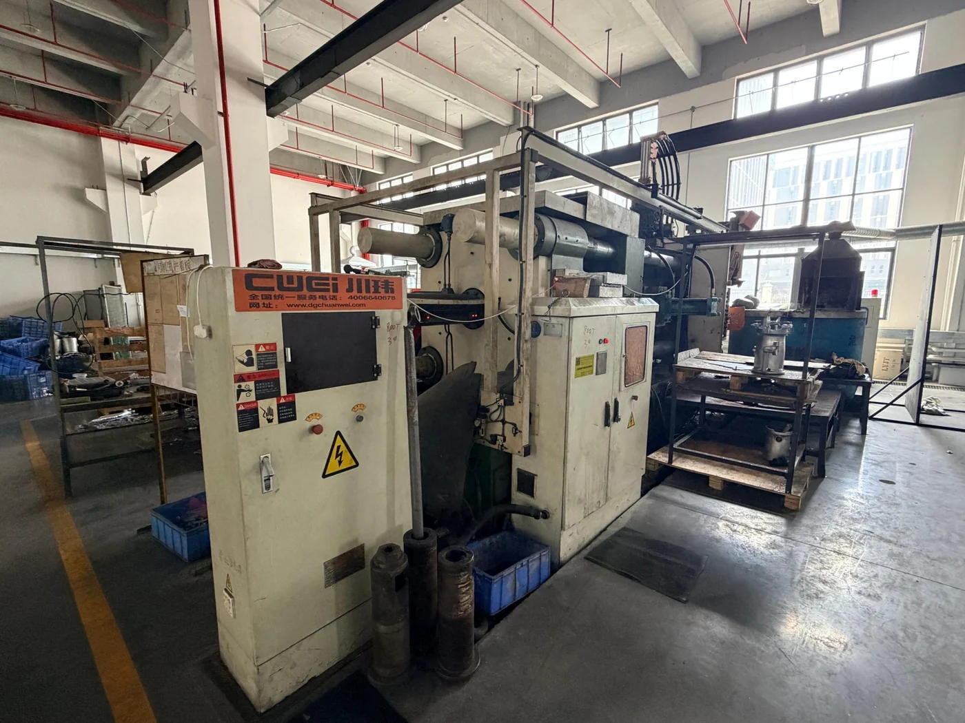
Coordinate the casting and secondary operations around the part you need to receive. The drawing, operating requirements and final delivery condition guide the manufacturing route.
Review tooling, critical interfaces, surface requirements and inspection before production.
Get in touchChoose the casting alloy for the combined thermal, structural, environmental and manufacturing requirements. Integrated shapes may suit die casting; long constant-section heat sinks may merit comparison with extrusion and machining.
| Material or route | Typical consideration | Confirm for your project |
|---|---|---|
| Aluminum die casting | Housings, structural features and thermal components | Alloy grade, functional geometry, temperature and secondary machining |
| Zinc die casting | Compact detailed parts and suitable decorative applications | Mass, sustained load, service temperature and finish compatibility |
| Machined interfaces | Holes, mounting faces, threads and sealing features | Datums, tolerances, surface condition and measurement method |
| Surface finishing | Appearance and environmental protection | Approved sample, coating-free areas, final fit and applicable tests |

Review appearance samples, preparation, masking and the surfaces that must retain a functional fit. Define the relevant test conditions and acceptance criteria with the part requirements.
Review material and finish requirementsConnect each project requirement to the manufacturing step and evidence needed to confirm it.
Identify the functional features and agree how they will be checked against the drawing.
Keep the requirements and approved references available at the relevant project stage.
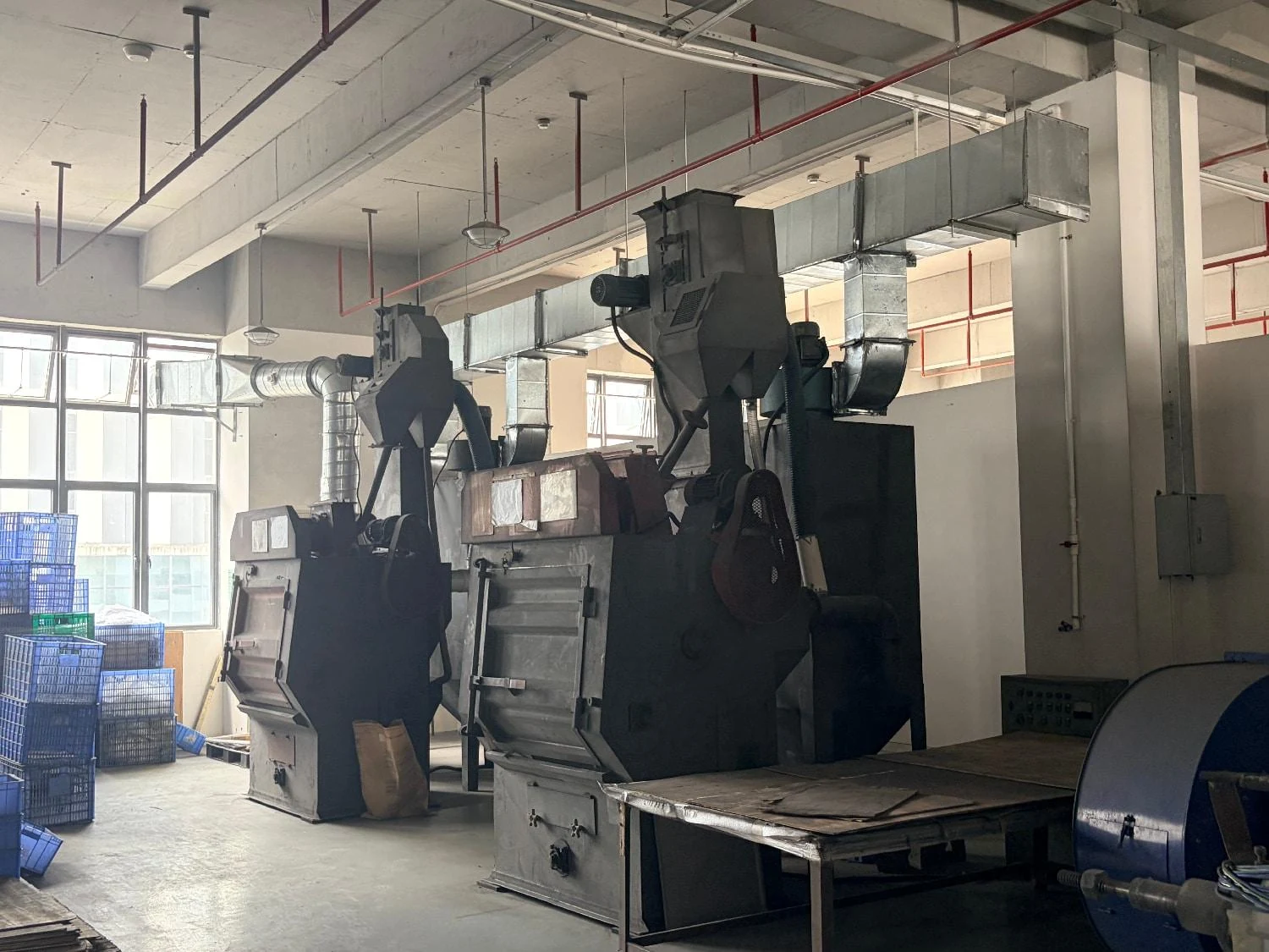
Review the operation and setup around the interfaces that affect your assembly.
Define what must be protected, finished or checked in the final delivered condition.
Confirm the part, sample or assembly inputs required for the agreed verification.
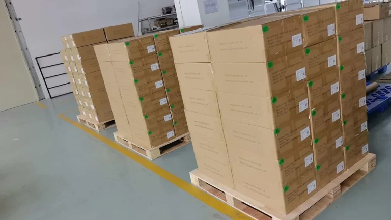
Match handling and packing to the geometry, surface and next assembly operation.
The inspection scope, records and delivery requirements are agreed for the specific part and its intended use.