Interfaces defined before finishing
- Thermal contact and mounting faces
- Conductive joints and grounding points
- Masking boundaries on the drawing
- Final-state surface requirements


Coordinate thermal contact, conductive interfaces and sealing in one enclosure
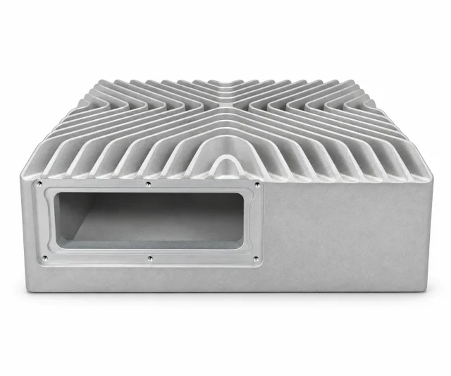
01 · Engineering support
A protective finish and a conductive joint do different jobs. Mark the grounding points, gasket contact lands and other electrical interfaces separately from the external painted surfaces. Review the permitted surface condition, masking boundary and checks for these areas before finishing begins. The finished drawing should also account for the dimensions that matter after coating. This approach lets the enclosure protect exposed surfaces while preserving the intended contact path. RF and EMC performance still needs verification in the complete equipment configuration, with the actual joint and gasket arrangement.
Discuss your requirements
02 · Engineering support
A larger housing or more fins will not resolve every temperature problem. Start with the location and size of the heat source, its contact to the housing and the available path into the surrounding air. Identify the base areas that need controlled flatness, finish or machining, and confirm how the equipment will be mounted. The alloy and geometry can then be assessed around the actual thermal layout. Thermal measurements should state the power, ambient conditions and assembly arrangement so the results remain relevant to the equipment you are developing.
Discuss your requirements
03 · Engineering support
An outdoor enclosure relies on more than the cast box. Lid flatness, gasket placement, groove geometry, fastener spacing and tightening conditions all influence the assembled interface. Review the enclosure with the actual sealing components and any cable or connector openings. Confirm the protection target and the configuration to be tested, including changes introduced by machining and finishing. The supporting report should identify that configuration and its acceptance conditions. This makes the supply scope clear and helps prevent a general material description from being mistaken for a verified enclosure rating.
Discuss your requirementsSeparate the protective enclosure, thermal body and internal mounting frame. Review conductive contacts, heat-transfer interfaces and the complete sealing arrangement together.
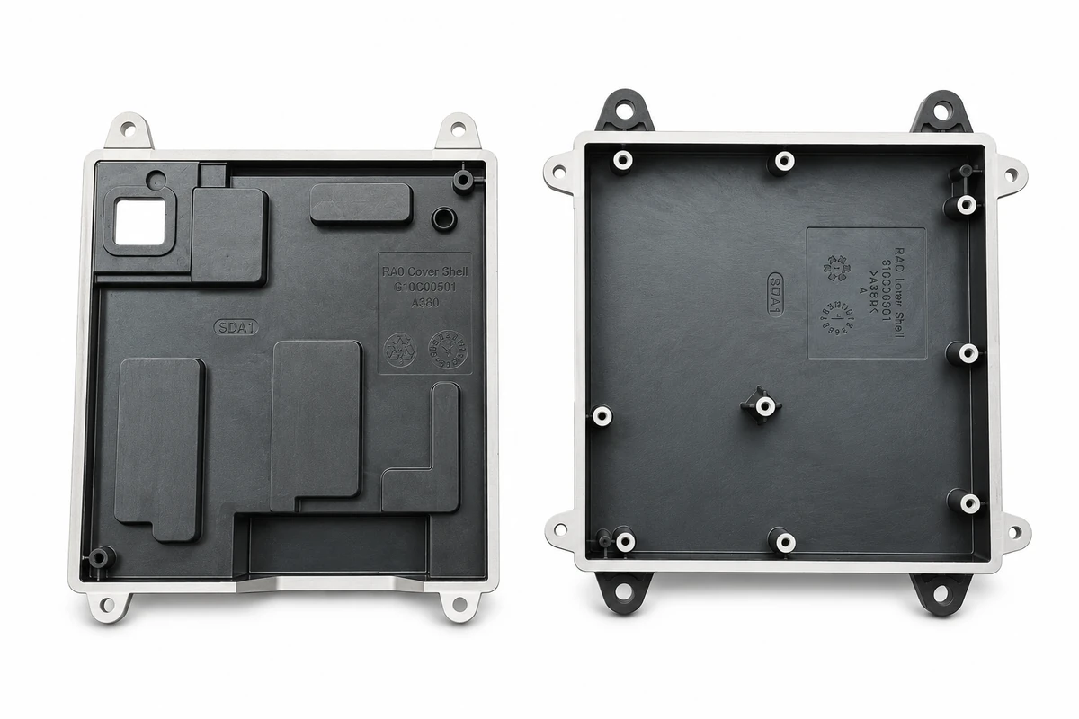
Locate electronic modules and protect them within a defined cover assembly.
Review: Sealing faces · cable openings · conductive contacts
Explore this part family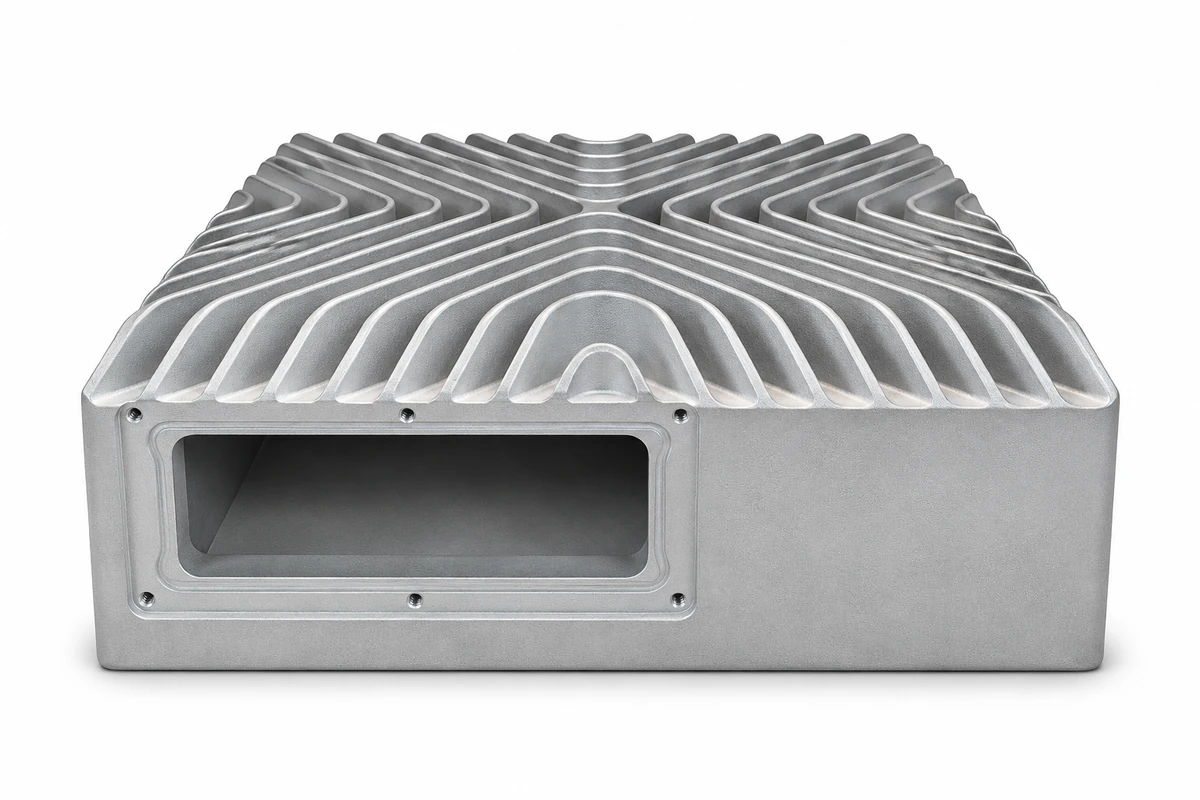
Carry heat from a defined contact area into the housing and fins.
Review: Contact flatness · fin geometry · thermal test conditions
Explore this part family
Locate boards and modules within the equipment package.
Review: Hole patterns · connector clearance · coating keep-out areas
Explore this part familyRepresentative component illustrations. Final geometry, alloy, finish and acceptance criteria are reviewed against your drawing and application.
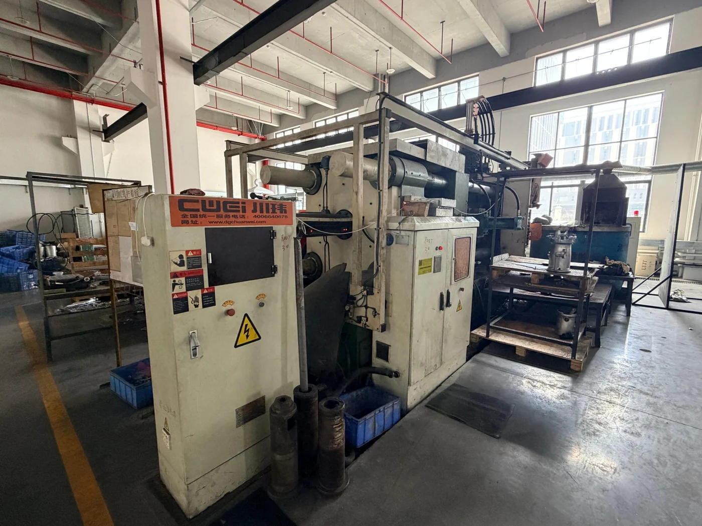
Coordinate the casting and secondary operations around the part you need to receive. The drawing, operating requirements and final delivery condition guide the manufacturing route.
Review tooling, critical interfaces, surface requirements and inspection before production.
Get in touchReview casting alloy properties against heat transfer, strength, environment and manufacturability. Thermal values must correspond to the selected alloy. Coating, conversion treatment, conductive surfaces and machining are defined by functional region.
| Material or route | Typical consideration | Confirm for your project |
|---|---|---|
| Aluminum die casting | Housings, structural features and thermal components | Alloy grade, functional geometry, temperature and secondary machining |
| Zinc die casting | Compact detailed parts and suitable decorative applications | Mass, sustained load, service temperature and finish compatibility |
| Machined interfaces | Holes, mounting faces, threads and sealing features | Datums, tolerances, surface condition and measurement method |
| Surface finishing | Appearance and environmental protection | Approved sample, coating-free areas, final fit and applicable tests |

Review appearance samples, preparation, masking and the surfaces that must retain a functional fit. Define the relevant test conditions and acceptance criteria with the part requirements.
Review material and finish requirementsConnect each project requirement to the manufacturing step and evidence needed to confirm it.
Identify the functional features and agree how they will be checked against the drawing.
Keep the requirements and approved references available at the relevant project stage.
Review the operation and setup around the interfaces that affect your assembly.
Define what must be protected, finished or checked in the final delivered condition.
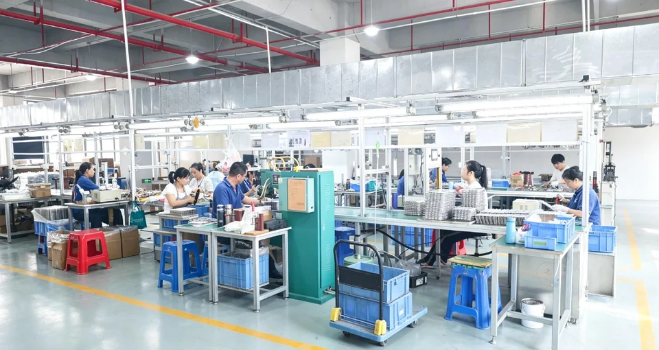
Confirm the part, sample or assembly inputs required for the agreed verification.
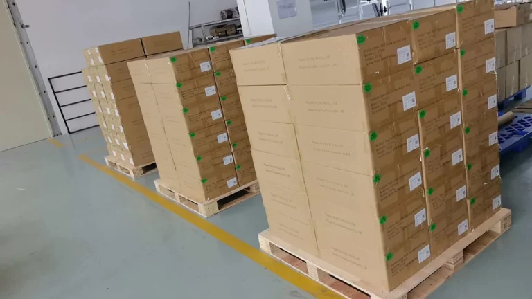
Match handling and packing to the geometry, surface and next assembly operation.
The inspection scope, records and delivery requirements are agreed for the specific part and its intended use.