Skip to content
MSdean
Contact Us

Assembly & Testing for Die-Cast Components

Parts brought together.
Ready for your next step.

MSdean connects die casting, machining and finishing with component assembly and agreed final checks, so you receive parts prepared for the next stage of production.

From individual parts to a defined subassembly
  • Assembly planned from your drawing and bill of materials
  • Fasteners, inserts, seals and mating features reviewed together
  • Sample approval and project-specific checks before release
Get in touch
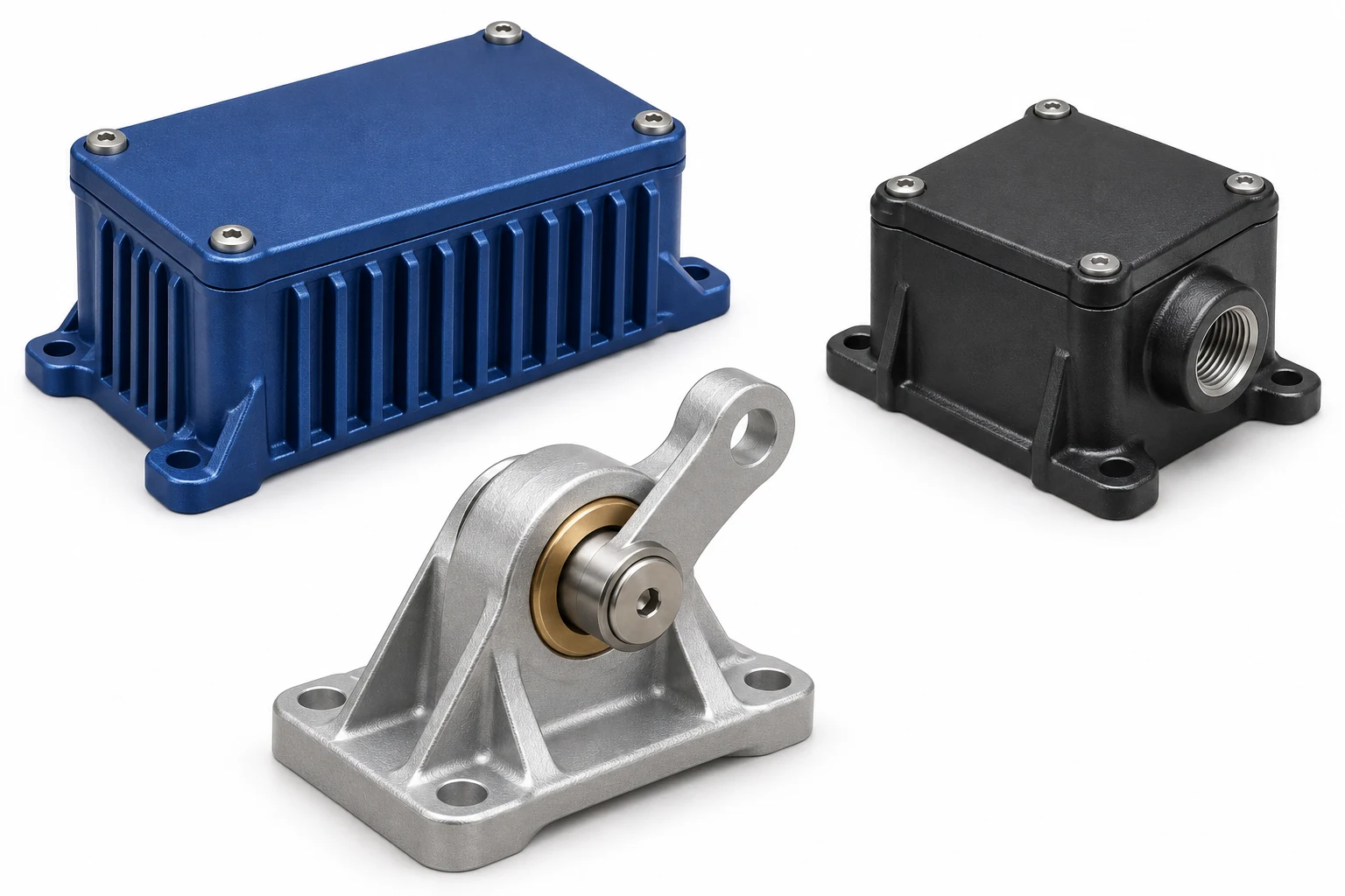
Illustrative aluminum and zinc component subassemblies
Component assembly · concept illustration
BOM-ledThe agreed components and revisions
Critical fitsInterfaces considered together
Defined checksAcceptance set for your project
Protected deliveryPacking suited to the assembly

Build the Assembly Around Your Product

Bring the component drawing, the mating parts and the final acceptance requirements into the same discussion.

Assembly sequence

Plan how the parts
come together.

A subassembly starts with more than a list of components. The order of work, access to fixing points and protection of finished surfaces all affect how the result is built.

  • Drawing & BOMConfirm part numbers, quantities, revisions and which items are supplied with the project.
  • Assembly accessReview tool clearance, locating features and the order of fitted components.
  • Surface protectionPlan handling and contact points around the finished appearance.
Review your assembly scope
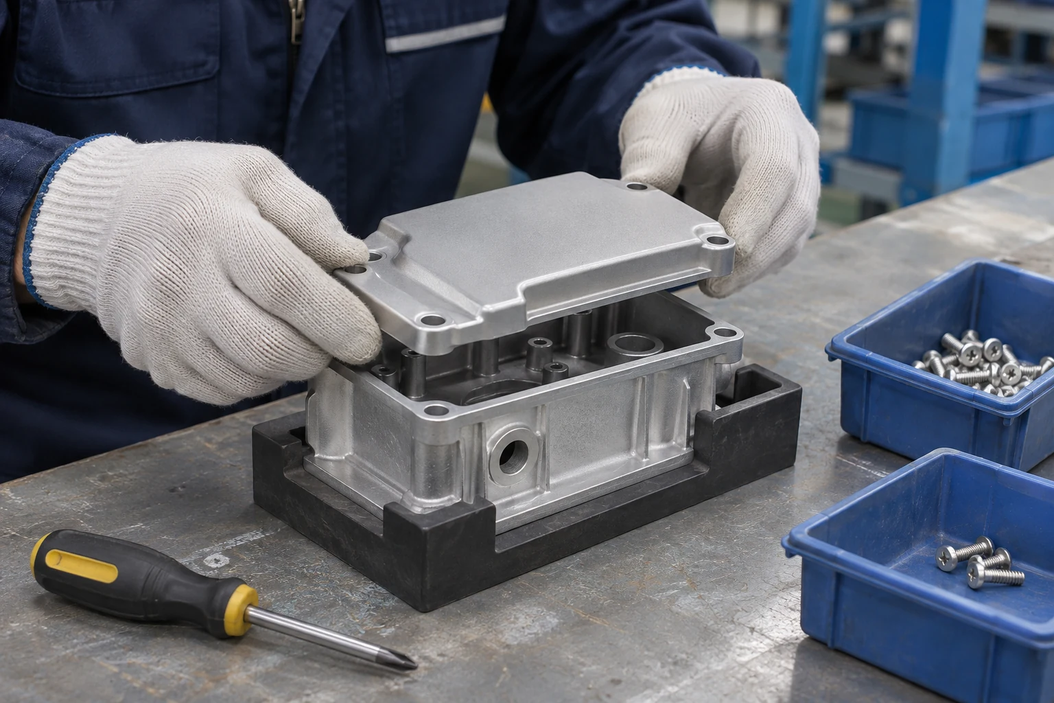
Illustrative mechanical assembly of a die-cast enclosure at a workbench
Fastening & interfaces

The connection matters
as much as the component.

Threads, inserts, seals and mating parts need a common plan. We review the joint requirements with machining and finishing before the assembly route is agreed.

  • Fasteners & insertsSpecify the item, installation method and any required tightening instructions.
  • Fits & alignmentIdentify locating faces, mating dimensions and the features that control assembly position.
  • Seals & contact surfacesConfirm seal type, seating condition and any material or finish compatibility requirements.
Explore assembly operations
Illustrative controlled fastening of a metal component assembly
Checks & release

Define what a good
assembly needs to do.

Appearance, dimensions and movement may each need a different check. Agree the inspection points and acceptance criteria so approval follows a clear reference.

  • Drawing-based inspectionIdentify critical dimensions and the required inspection records.
  • Fit & functionAgree mating-part trials, movement or other checks relevant to the assembly.
  • Special test requirementsShare the method and limits early so feasibility, equipment and responsibility can be confirmed.
Discuss inspection requirements
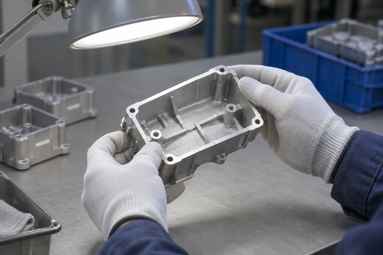
Illustrative dimensional verification of a metal housing assembly

Generated illustrations show representative assembly operations and checks. They are not photographs of MSdean equipment or customer projects.

Explore Assembly & Final Checks

Select an operation to see what needs to be defined. The scope is confirmed for your drawing, components and acceptance requirements.

Illustrative mechanical assembly of die-cast components

A planned component sequence

Bring the parts into one usable subassembly

Housings, covers, brackets and other components are brought together according to the agreed drawing and assembly instructions.

  • Component scope and supply responsibility confirmed
  • Locating features and access to fixing points reviewed
  • Work sequence developed around the part geometry
Review a mechanical assembly

From Assembly Brief to Protected Delivery

Keep component preparation, assembly instructions and acceptance checks connected throughout the project.

  1. Illustrative finished component subassemblies for planning
    01

    Define the Scope

    Confirm the assembly drawing, BOM, revisions and supply responsibilities.

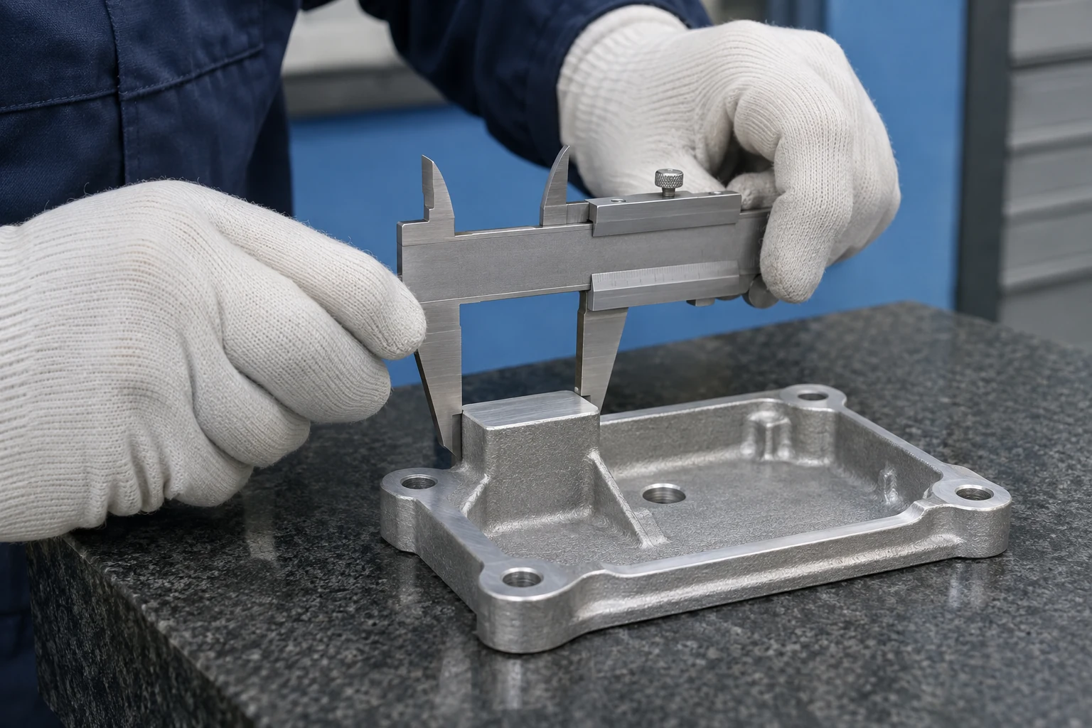
  2. Illustrative verification of incoming assembly features
    02

    Check the Components

    Review the specified dimensions, condition and required component identification.

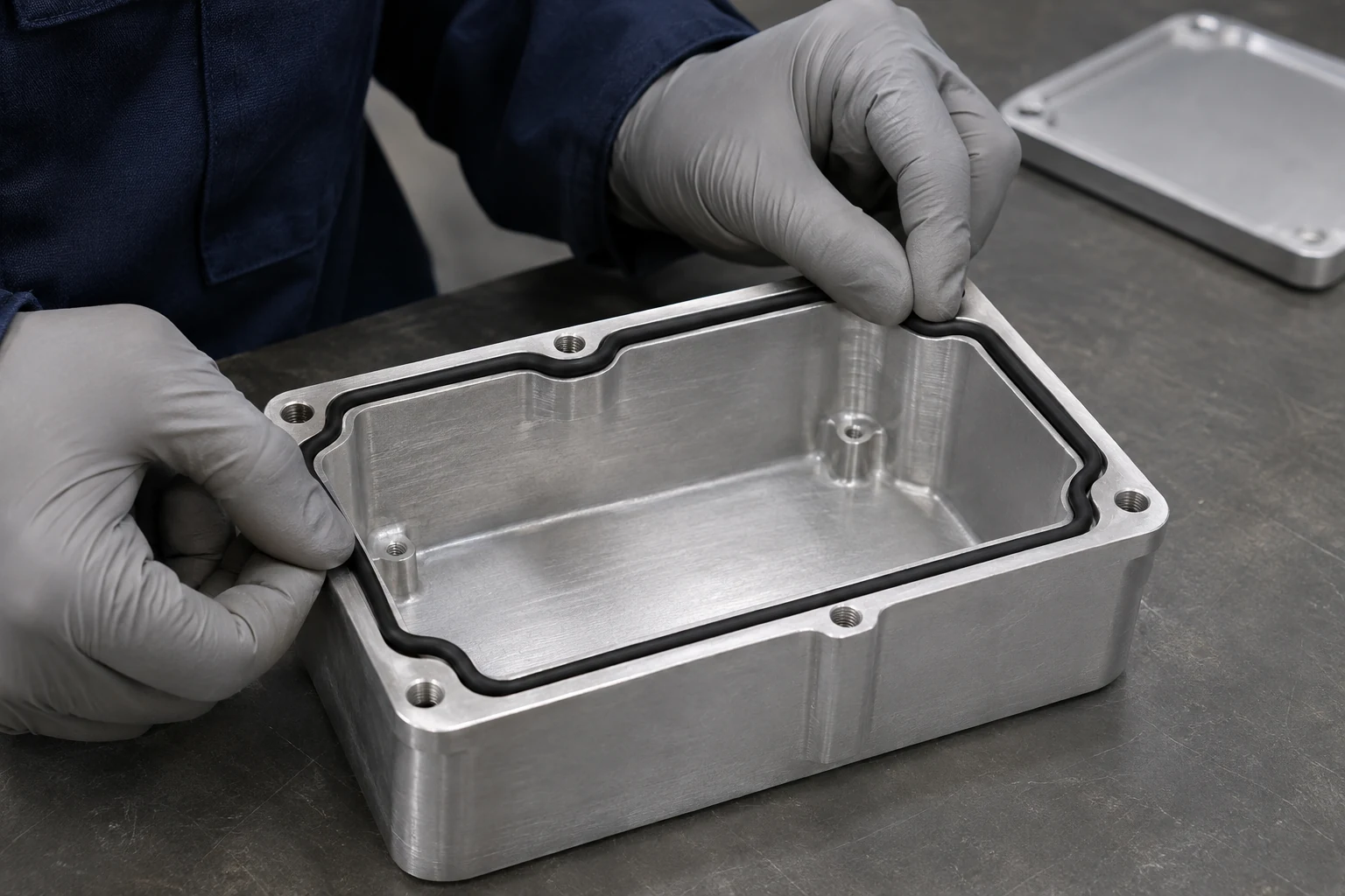
  3. Illustrative preparation of a gasket and enclosure
    03

    Prepare the Interfaces

    Plan clean contact surfaces, seal seating and the required assembly orientation.

  4. Illustrative mechanical component assembly
    04

    Assemble to the Plan

    Bring the components together using the agreed sequence and instructions.

  5. Illustrative fit and function check on a mechanical assembly
    05

    Verify the Result

    Check the agreed dimensions, fit, appearance and project-specific requirements.

  6. Illustrative protective packing of completed assemblies
    06

    Pack for Delivery

    Protect the assembly and apply the agreed identification and packing format.

Agree the Checks Before Production

A clear inspection plan defines what is checked, how it is checked and what makes the assembly acceptable.

Dimensions & Mating Features

Define the dimensions that control the assembly. The inspection plan should connect individual component requirements with the features needed for the finished fit.

  • Critical dimensions and drawing revisions
  • Locating faces, alignment and mating features
  • Inspection method and required records
Fasteners, Inserts & Seals

Agree the required items and their installed condition. Tightening, insert installation and seal seating requirements need to be defined for the particular joint.

  • Correct component identification and presence
  • Orientation, seating and installation requirements
  • Specified tightening instructions where applicable
Function & Project-Specific Tests

Fit, movement or other performance checks follow the application. For leak, pressure, electrical or other special testing, share the method and limits so feasibility, equipment, responsibility and reporting can be agreed before quotation.

  • Test conditions and acceptance criteria
  • Required frequency and lot- or revision-linked records
  • Any specialist testing confirmed in the project scope
Illustrative dimensional inspection of a metal assembly
Drawing and fit review · process illustration

Fewer Open Questions at Handover

One Assembly Brief

Keep the drawing, BOM, component supply and acceptance requirements in one agreed scope.

Connected Operations

Consider casting, machining and finishing with the interfaces used during assembly.

A Defined Reference

Review samples and the required checks before the production route is released.

Ready for Handling

Plan identification and protective packaging around the completed subassembly.

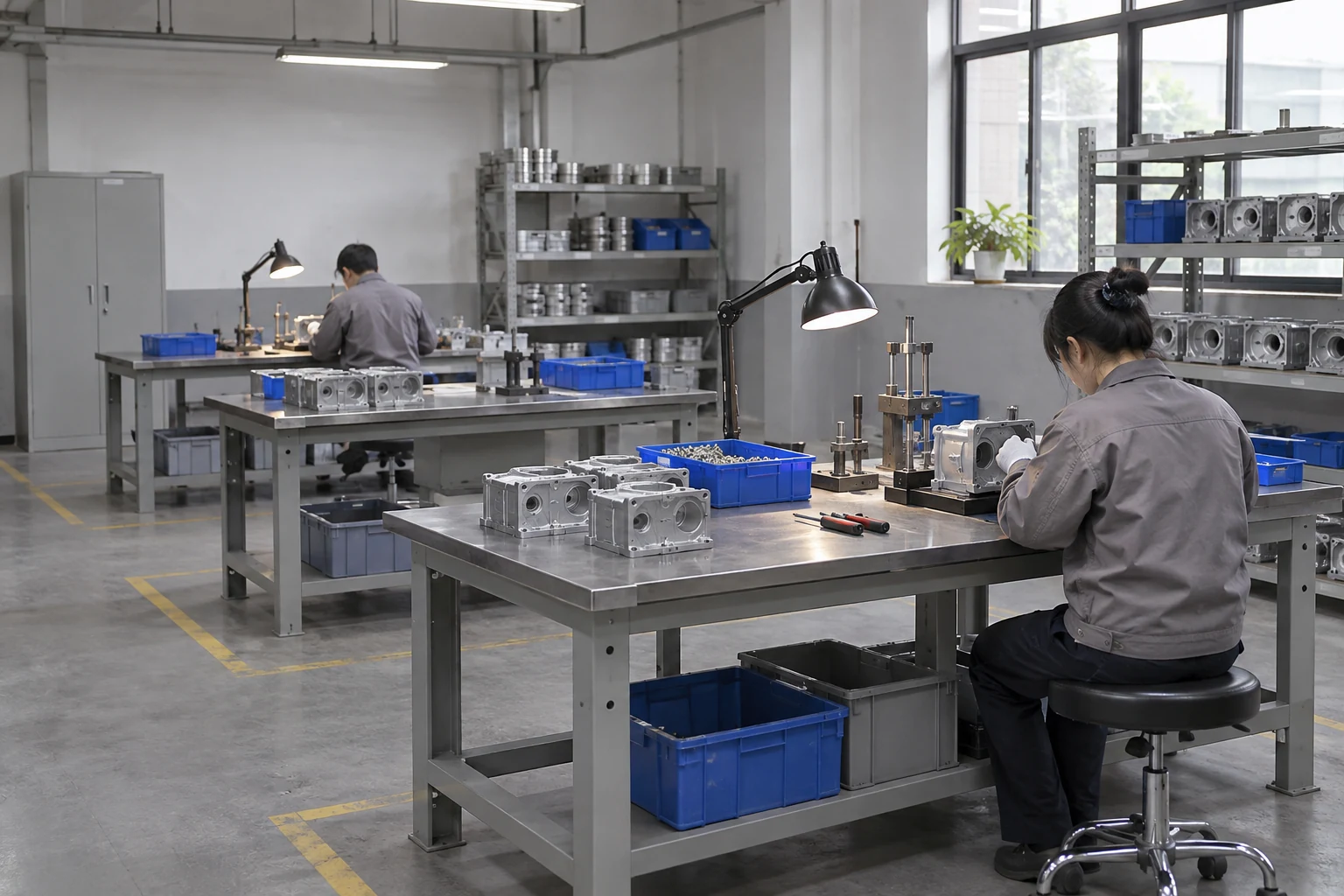
Illustrative component assembly workstations and material flow
Assembly workflow illustration

Assembly Within the Production Route

A connected process.
A clearer handover.

Plan the die-cast part, its machined features, its finish and the fitted components together. The assembly scope should make the next stage of your production easier to manage.

Review your assembly requirements

Start with a Clear Assembly Brief

Your component list and acceptance requirements help turn an assembly idea into a practical quotation.

What to Send

  • Assembly drawing, component drawings and current revisions
  • Bill of materials and component supply responsibilities
  • Fitted items, fasteners, inserts, seals and mating references
  • Installation instructions and critical assembly features
  • Required checks, test methods, limits and reporting
  • Quantity, sample approval, packaging and target timing
Before Production Release

Approve the assembly.
Confirm the acceptance.

Review the sample with the drawing and BOM. Record the agreed installation instructions, acceptance criteria, inspection records and any open points before production begins.

Discuss your project

Assembly & Testing FAQs

What information is needed for an assembly quotation?

Send the assembly drawing, the current BOM and the drawings of the components involved. Identify which items you supply, the quantities, the required checks and any packaging instructions. Mating samples or reference parts are useful when the fit cannot be fully described by the drawings.

Can supplied components be included in the assembly?

Customer-supplied items can be reviewed as part of the project scope. Confirm their specification, revision, quantity, delivery condition and responsibility for incoming acceptance. These details need to be agreed before the assembly plan is finalized.

How are fastener and insert requirements defined?

Specify the item and its installed condition in the BOM or assembly instructions. Include any required installation method, tightening sequence or torque specification for the particular joint. The receiving features, finish and tool access should be reviewed together.

Does fitting a seal guarantee that the assembly is leak-tight?

No. Seal selection and correct seating are only part of the requirement. The mating geometry, surface condition and operating conditions also matter. If leak or pressure testing is required, state the method, test conditions, limits and reporting so the test scope can be reviewed and agreed.

Which tests can be included with an assembly?

The required checks are reviewed for the particular product. These may include dimensions, appearance, fit or movement. Leak, pressure, electrical or other specialist tests require an agreed method, acceptance limits and confirmation of feasibility, equipment, responsibility and reporting before quotation.

How are the assemblies identified and packed?

Identification, packing quantity and protection are agreed with the order. Labels, lot references or inspection records can be included where specified and confirmed. Packaging should protect finished surfaces and fitted components during the expected handling route.

Let’s Review
Your Assembly Project

Send your drawing and BOM, and tell us what the finished assembly needs to do. MSdean will review the component scope, assembly route and quotation with you.

  • Component and supply responsibility review
  • Fastening, sealing and mating feature planning
  • Sample approval and agreed inspection requirements
  • One contact from casting to finished subassemblies
info@msdeanmfg.com

Tell us about your project

Start with the details you have.

Portfolio preview. This form is for demonstration only.

The details you provide will be used to respond to your project inquiry.

Discuss your project

Share your part drawing, material and expected quantity.

Portfolio preview. This form is for demonstration only.

The details you provide will be used to respond to your project inquiry.