Skip to content
MSdean
Contact Us
Manufacturing resources

Die casting defects guide

Recognize 11 surface and edge indications, compare possible contributing factors and plan the next inspection.

Coverage
11 defect types
Method
Appearance + process review
Focus
Casting & handling
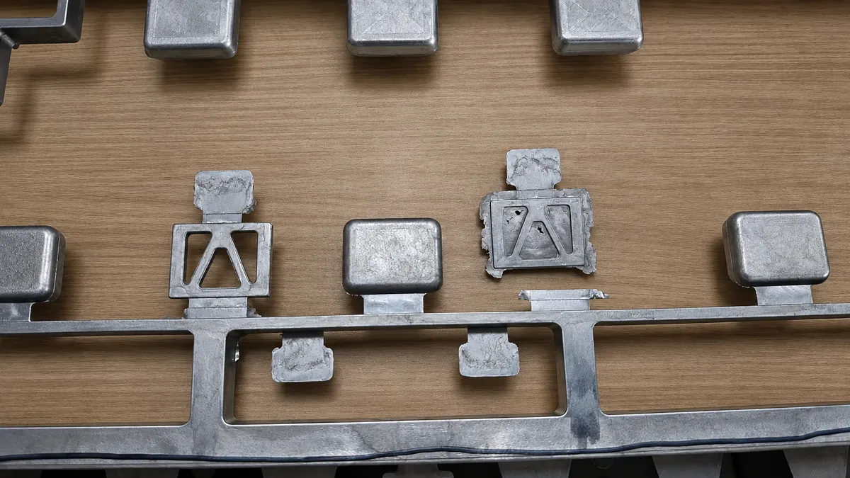
Die-cast components and runner material from the supplied process reference

Find the indication on your part

Search by defect name, appearance or control point. Open a card to review the possible contributing factors.

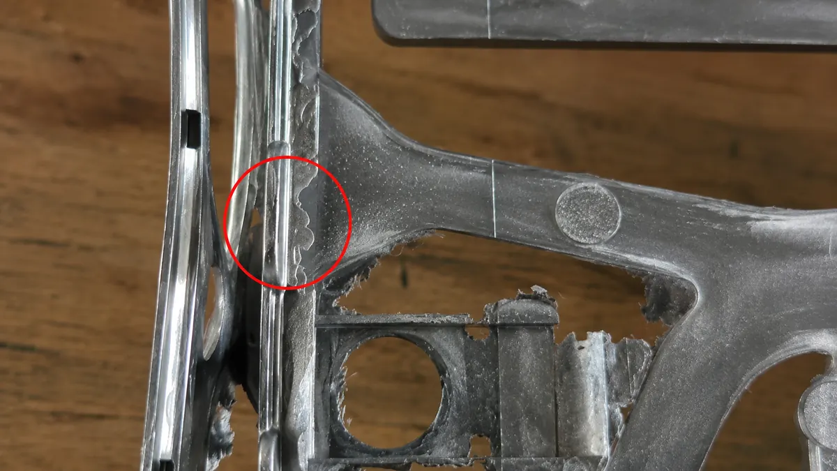
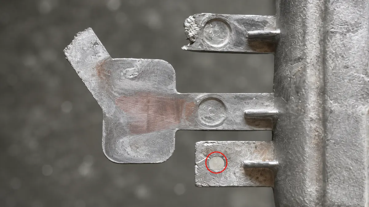
Soldering / die sticking indication in the supplied die-casting defect reference
Tooling & release

Soldering / die sticking

Irregular torn patches and rough, pulled-away material without a consistent direction.

Review causes & control points

Possible contributing factors

Local die overheating, release coverage and adhesion to the tool may contribute.

Control points to review

Review thermal balance, release application and the condition of the affected die area.
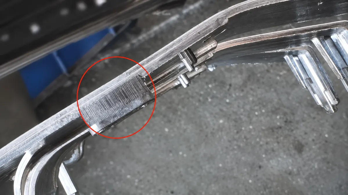
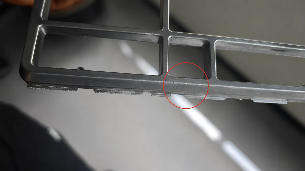
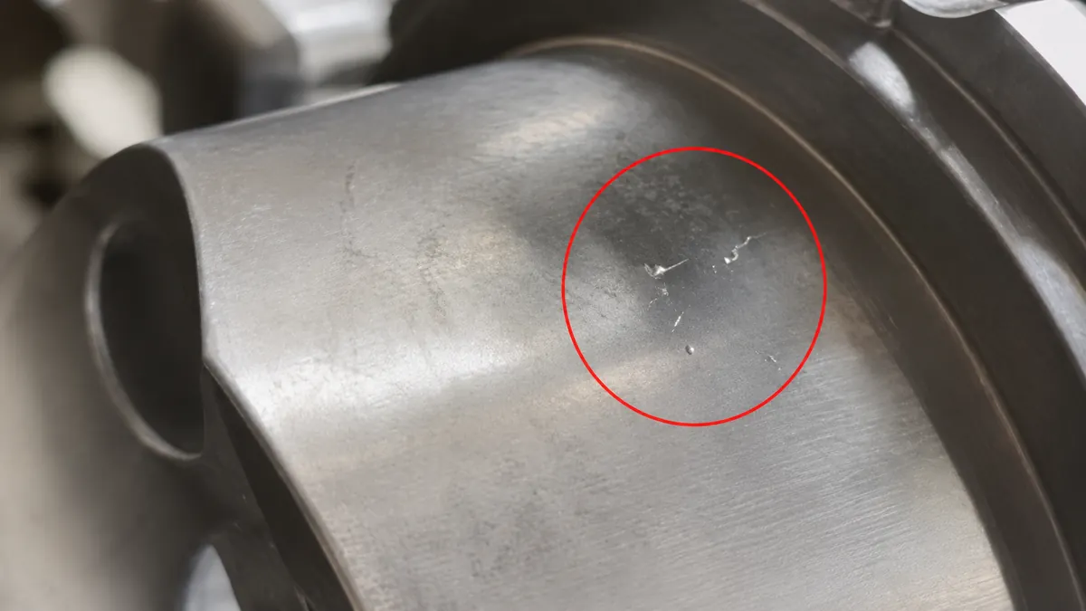
Drag marks indication in the supplied die-casting defect reference
Tooling & release

Drag marks

Parallel grooves or long marks that follow the direction of release from the die.

Review causes & control points

Possible contributing factors

Insufficient draft, a rough tool surface or interference during ejection may contribute.

Control points to review

Check draft and surface condition; review the alignment and sequence of release.

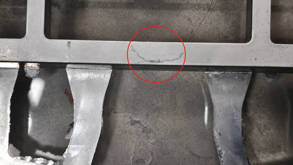
Cold shuts indication in the supplied die-casting defect reference
Filling

Cold shuts

A seam or line where metal fronts meet without joining completely.

Review causes & control points

Possible contributing factors

Low local temperature, a long flow path or unsuitable filling conditions may contribute.

Control points to review

Review die and melt temperatures together with filling, gating and overflow conditions.

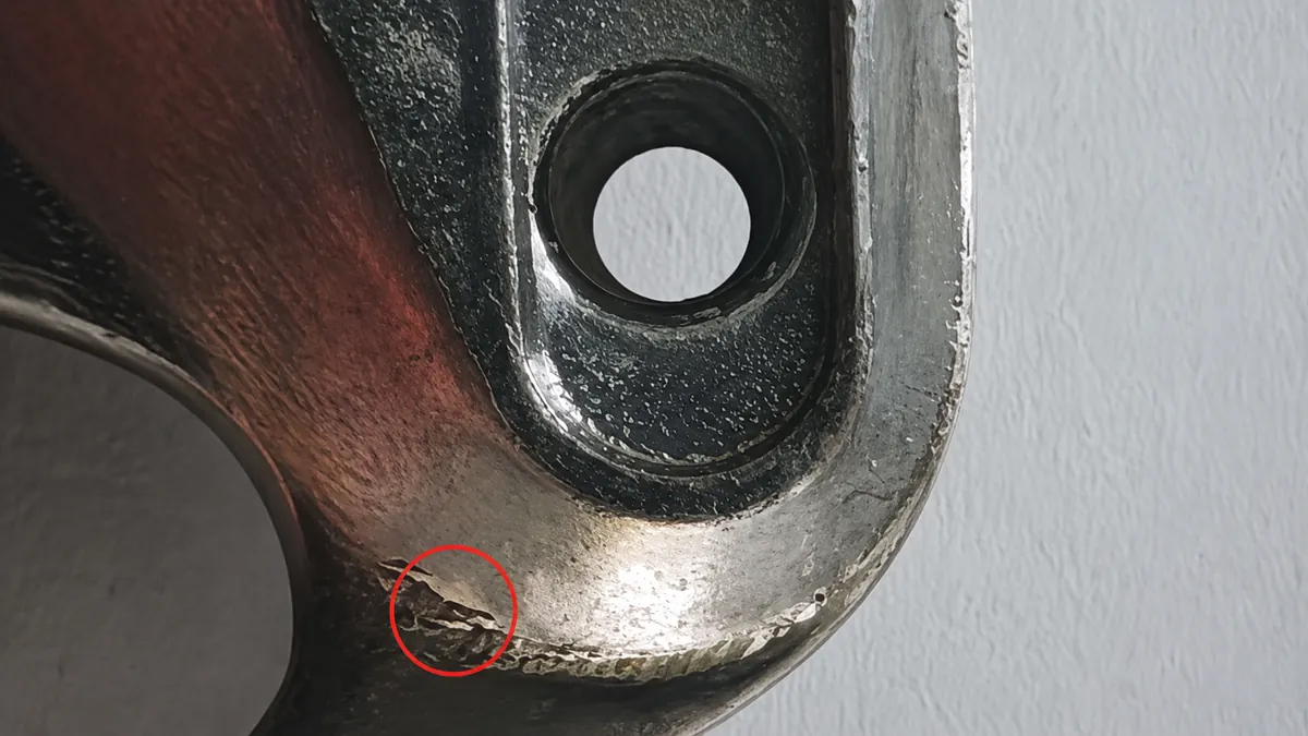
Edge chipping / breakage indication in the supplied die-casting defect reference
Tooling & release

Edge chipping / breakage

Missing fragments or sharp-edged notches at corners, thin ribs or other vulnerable areas.

Review causes & control points

Possible contributing factors

Weak local geometry, concentrated release forces or sticking may contribute.

Control points to review

Inspect vulnerable features and review tool release and support before accepting the part.

Flash indication in the supplied die-casting defect reference
Tooling & release

Flash

Thin excess metal along a parting line, slide boundary or insert edge.

Review causes & control points

Possible contributing factors

Tool gaps, wear, contamination or unsuitable clamping and injection conditions may contribute.

Control points to review

Check die closure and mating surfaces; review machine and process conditions before trimming.

Die erosion indications indication in the supplied die-casting defect reference
Tooling & release

Die erosion indications

Local raised material that repeatedly appears near a metal-flow impact area.

Review causes & control points

Possible contributing factors

Concentrated flow, thermal loading or wear at the impact area may contribute.

Control points to review

Inspect the corresponding die area and review flow direction, velocity and local cooling.

Sink marks indication in the supplied die-casting defect reference
Solidification & gas

Sink marks

Smooth depressions, often near thicker sections or behind ribs and bosses.

Review causes & control points

Possible contributing factors

Local solidification and feeding conditions, section changes or hot spots may contribute.

Control points to review

Review wall transitions, local thermal balance and the feeding or pressure sequence.

Cold material marks indication in the supplied die-casting defect reference
Filling

Cold material marks

A distinct patch or scar with a texture or appearance different from the surrounding metal.

Review causes & control points

Possible contributing factors

Prematurely cooled metal and the filling or overflow arrangement may contribute.

Control points to review

Review melt consistency, filling conditions and the route used to collect cold leading metal.

Blisters indication in the supplied die-casting defect reference
Solidification & gas

Blisters

Raised areas on the surface that can be associated with gas below the casting skin.

Review causes & control points

Possible contributing factors

Entrapped gas, venting and release-agent application may contribute.

Control points to review

Investigate gas sources and venting; review filling and thermal conditions against process records.

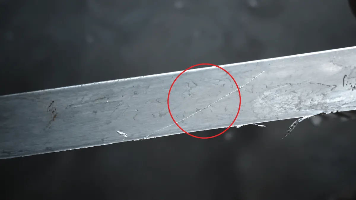
Scratches indication in the supplied die-casting defect reference
Handling

Scratches

Shallow lines with varying length and direction, without a large torn area.

Review causes & control points

Possible contributing factors

Contact with rough tooling, interference or residue during release may contribute.

Control points to review

Identify the contact point; check tool surfaces, clearance and handling protection.

Dents / impact damage indication in the supplied die-casting defect reference
Handling

Dents / impact damage

Local indentations, flattened corners or compressed edges.

Review causes & control points

Possible contributing factors

Ejection, removal, dropping or contact with other parts may contribute.

Control points to review

Review removal and transfer paths, isolate parts in suitable trays and protect vulnerable edges.

Confirm the cause: a similar appearance can have more than one cause. Review the affected feature, tooling and process records before selecting a corrective action.

Connect the indication to the process

Record the location

Identify the surface, cavity and operation where the indication appears. Compare the part with the agreed reference.

Review the contributing conditions

Check the relevant filling, thermal, release or handling conditions. Treat the listed factors as investigation prompts.

Verify the response

Confirm the proposed adjustment with engineering and check the resulting parts against the project acceptance criteria.

Questions about defect assessment

Can a photograph identify the root cause?

A photograph helps classify an indication. Its cause needs to be checked against the part geometry, tool condition and production records.

Is every surface mark a rejection?

The drawing, functional requirements and approved appearance limits govern acceptance. Agree the criteria for the relevant surface before production.

Can edge finishing correct every casting defect?

Edge finishing addresses defined burr and surface-preparation work. Structural concerns, incomplete filling or other casting defects need an engineering decision rather than a cosmetic assumption.

Technical references & scope

The photos in this guide come from MSdean’s training materials. For part acceptance, use the drawing and agreed inspection criteria.

Review the critical features on your casting

Share the drawing, finish requirement and any defect references that matter to your application.

Get in touch

Discuss your project

Share your part drawing, material and expected quantity.

Portfolio preview. This form is for demonstration only.

The details you provide will be used to respond to your project inquiry.