Assembly interfaces come first
- Bearing and shaft fit requirements
- Related datums and mounting faces
- Seal grooves and machined surfaces
- Threads, clearances and accessibility


Receive components in the condition your equipment assembly needs
01 · Engineering support
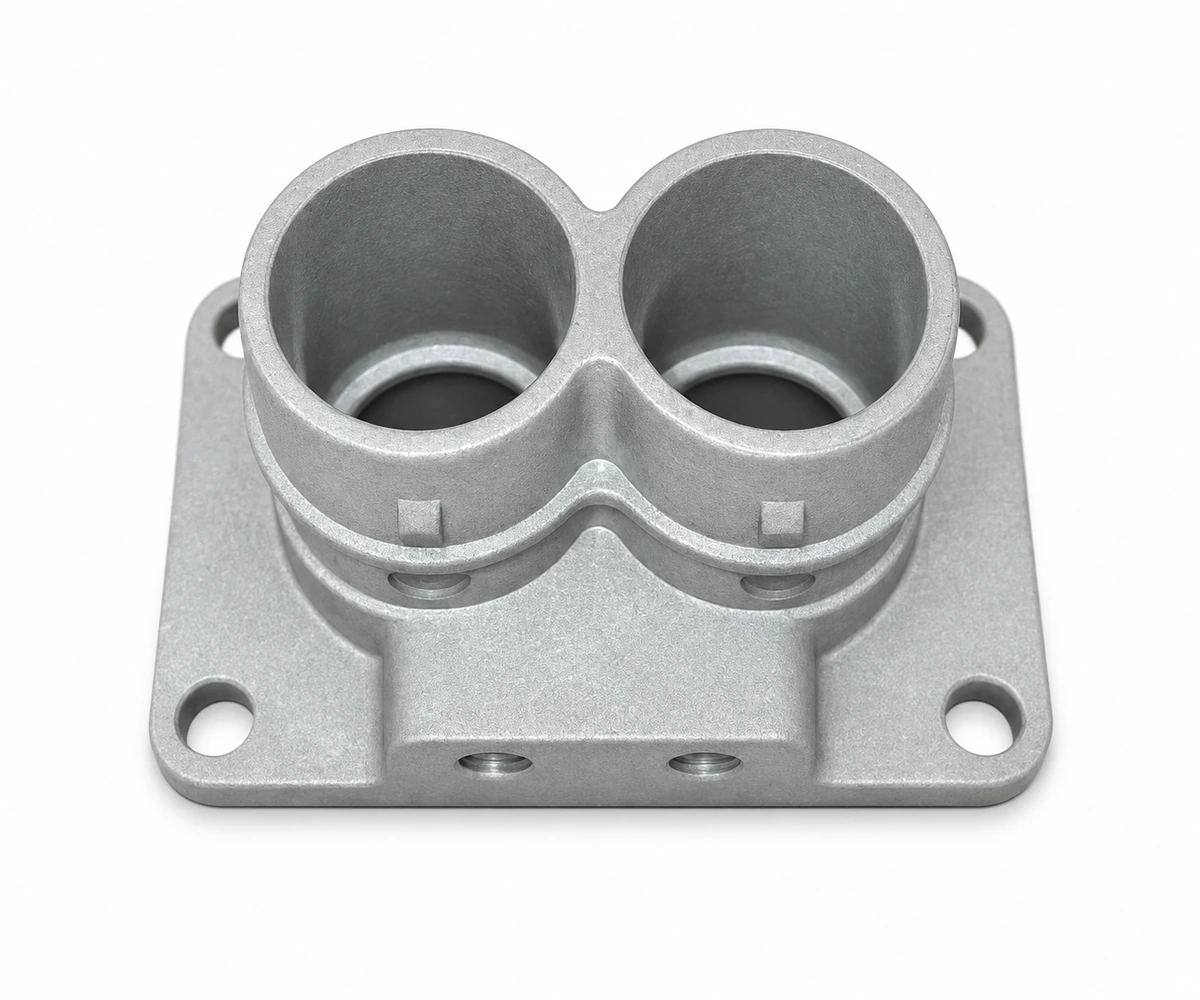
A housing can meet an individual bore size and still create an assembly problem if the related seats, shoulders and mounting faces are not aligned. Review the bearing arrangement and operating fit before choosing the machining sequence. The drawing should identify the functional datums and geometrical requirements as well as the bore dimensions. Inspection can then follow the same reference system used for manufacturing. This is particularly useful for motor covers, gearbox housings and actuator parts where several interfaces must work together after the part reaches your assembly line.
Discuss your requirements
02 · Engineering support
A pump cover or gearbox housing needs a sealing specification that describes how the finished part will be used. Identify the working medium, pressure, temperature, seal type and test stage, then review the surfaces and passages affected by machining. The inspection plan should distinguish the casting itself from the assembled housing with its gasket, fittings and fasteners. Where a leak check is required, agree the test method and acceptance value with the quotation. A defined requirement supports a practical process route and avoids discovering an undefined sealing expectation at final assembly.
Discuss your requirements
03 · Engineering support
The useful comparison is the part in its delivered condition. State whether the scope includes drilling, tapping, deburring, cleaning, finishing and assembly, and identify the areas that must remain free of coating or machining residue. Threaded holes and inaccessible internal passages deserve particular attention when you define inspection and packaging. For repeat orders, retain the approved drawing, finish sample and packing method together. This lets your team compare suppliers on the work still required after delivery, alongside the quoted price of the casting itself.
Discuss your requirementsConnect equipment structure, shaft support and mating faces to the assembly drawing. Review the dimensions and delivered condition needed at your production line.

Locate and support components within an equipment assembly.
Review: Load paths · boss geometry · locating faces
Explore this part familyHold related bores and mounting points in the required relationship.
Review: Bore size · alignment · clamping and inspection datums
Explore this part family
Establish mating faces and concentric connection features.
Review: Fits · axial faces · thread and seal requirements
Explore this part familyRepresentative component illustrations. Final geometry, alloy, finish and acceptance criteria are reviewed against your drawing and application.
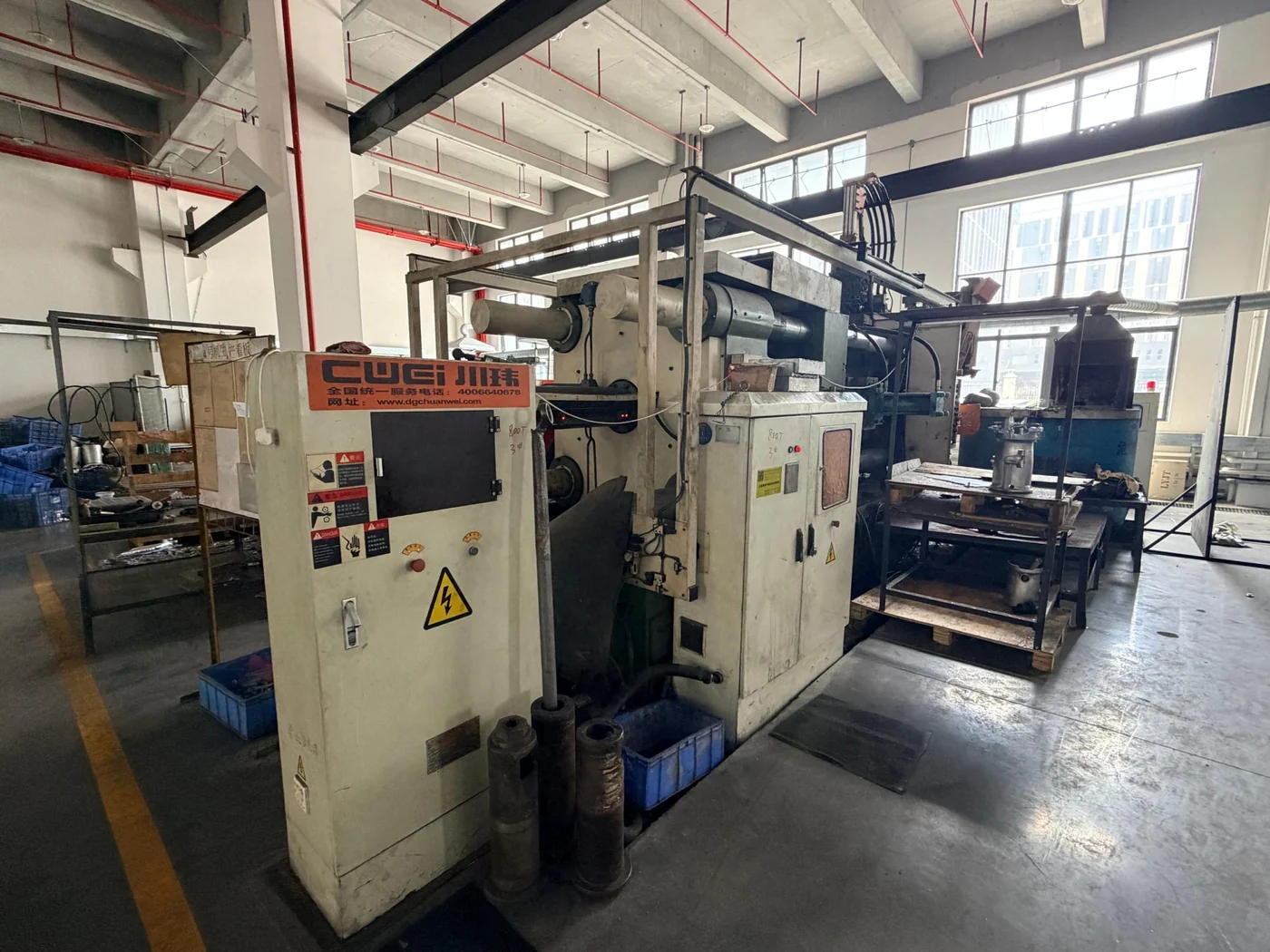
Coordinate the casting and secondary operations around the part you need to receive. The drawing, operating requirements and final delivery condition guide the manufacturing route.
Review tooling, critical interfaces, surface requirements and inspection before production.
Get in touchChoose aluminum or zinc against geometry, operating temperature, sustained load, mass and finishing requirements. For small quantities or changing designs, compare a machined route before committing to dedicated casting tooling.
| Material or route | Typical consideration | Confirm for your project |
|---|---|---|
| Aluminum die casting | Housings, structural features and thermal components | Alloy grade, functional geometry, temperature and secondary machining |
| Zinc die casting | Compact detailed parts and suitable decorative applications | Mass, sustained load, service temperature and finish compatibility |
| Machined interfaces | Holes, mounting faces, threads and sealing features | Datums, tolerances, surface condition and measurement method |
| Surface finishing | Appearance and environmental protection | Approved sample, coating-free areas, final fit and applicable tests |

Review appearance samples, preparation, masking and the surfaces that must retain a functional fit. Define the relevant test conditions and acceptance criteria with the part requirements.
Review material and finish requirementsConnect each project requirement to the manufacturing step and evidence needed to confirm it.
Identify the functional features and agree how they will be checked against the drawing.
Keep the requirements and approved references available at the relevant project stage.
Review the operation and setup around the interfaces that affect your assembly.
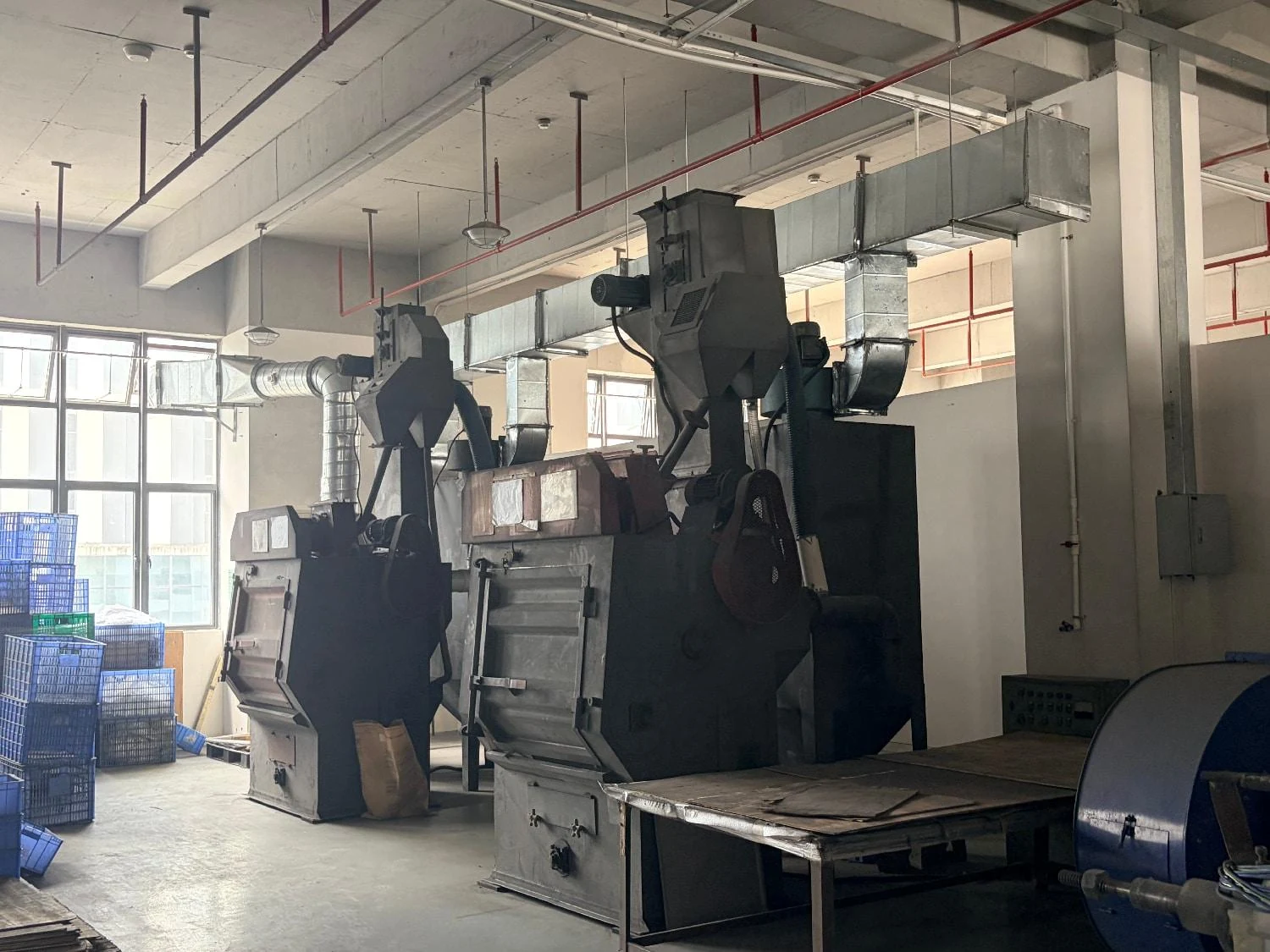
Define what must be protected, finished or checked in the final delivered condition.
Confirm the part, sample or assembly inputs required for the agreed verification.
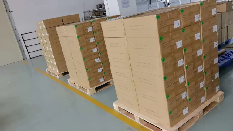
Match handling and packing to the geometry, surface and next assembly operation.
The inspection scope, records and delivery requirements are agreed for the specific part and its intended use.