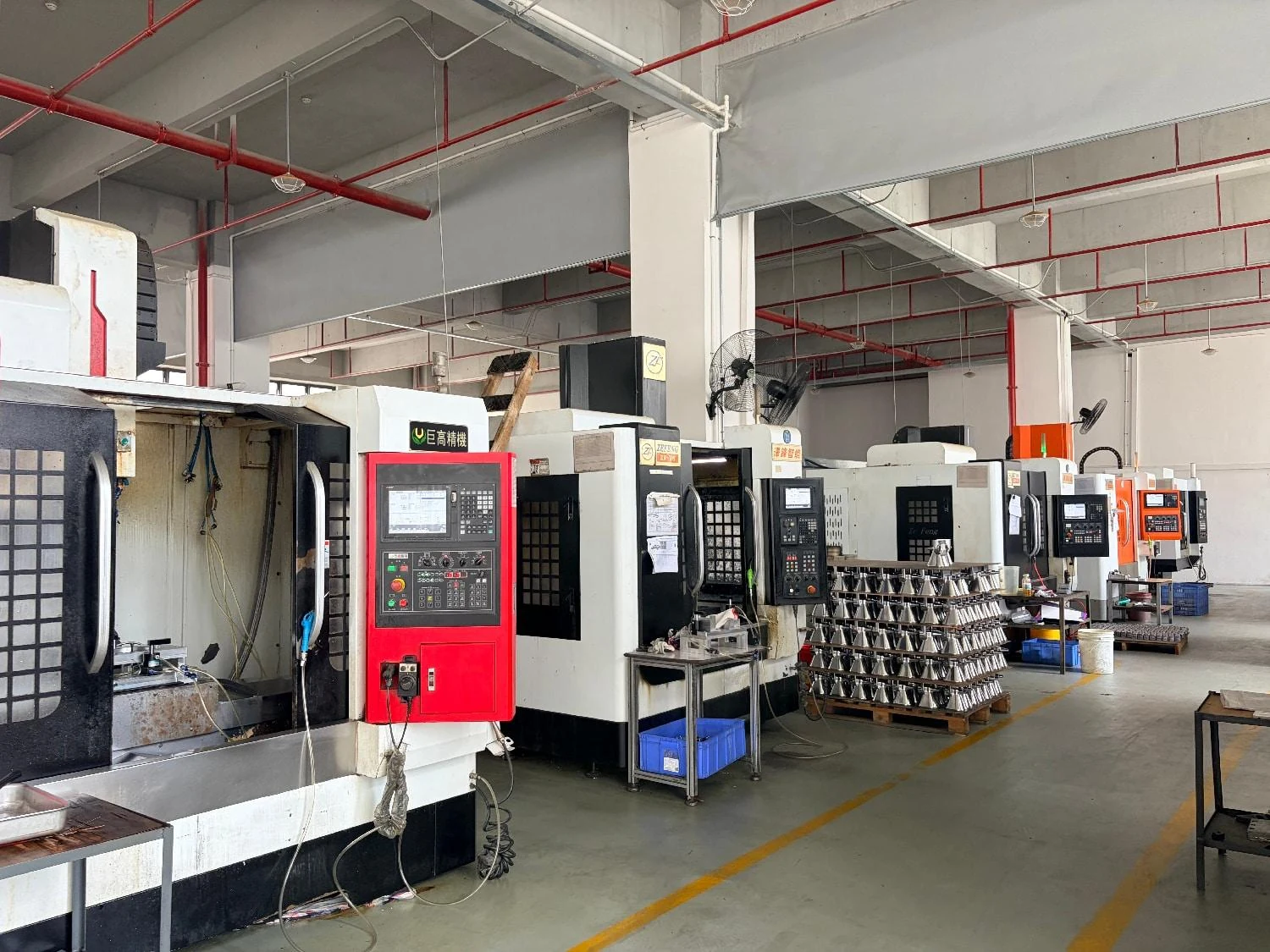
Heat source
Define the power input and operating conditions.

Heat-dissipation parts
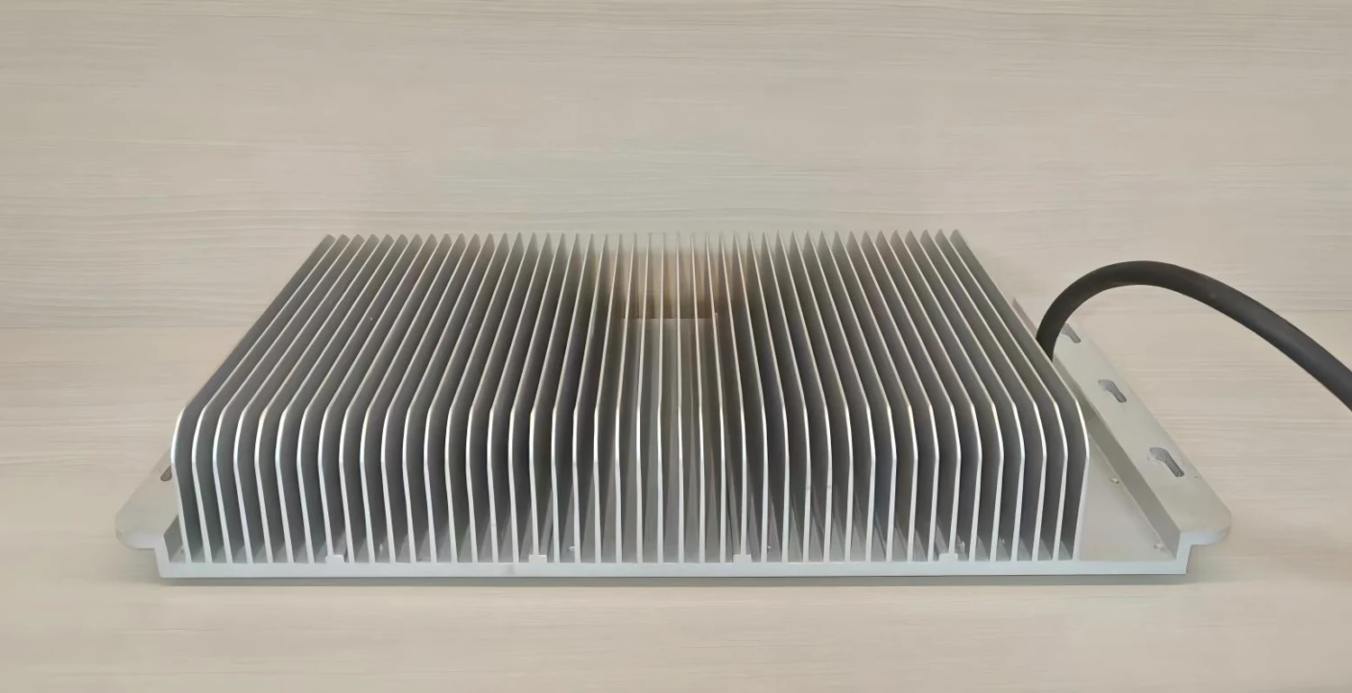
Custom finned components and thermal housings with casting, mounting features and machined contact surfaces coordinated for your product.
Review the complete path
Define the power input and operating conditions.
Specify the mating face and interface material.
Review alloy, geometry and mounting features.
Identify airflow, orientation and performance tests.
Function before form
Define the heat source, contact area, flatness, finish and interface material. The contact path can matter as much as the outside fin geometry.
Review fin depth, spacing, draft and release direction. A visually dense fin array needs a feasible tool and filling route.
Integrate fastener patterns and identify masked conductive or contact areas. State the coating and environment rather than relying on color alone.
Design context
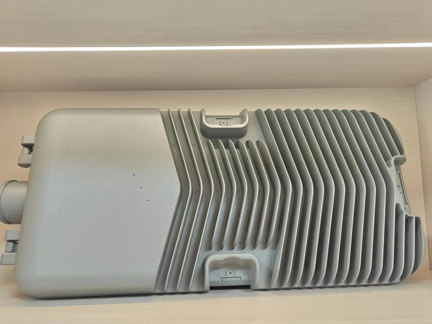
Extrusion, machining and die casting offer different design opportunities. Die casting may help integrate mounting and complex form, but the choice still depends on alloy performance, tool access, volume and secondary operations. Confirm thermal performance in the actual operating configuration.
Process selection / Geometry and performance
The best route depends on the required geometry, material properties, forecast and secondary operations. Use a process comparison before committing to a casting tool.
Integrated mounting bosses, complex external form and several features in one component can justify a casting review. Check alloy properties, fin release, filling, tool cost and the machined contact face.
A largely constant cross-section may warrant an extrusion comparison; early quantities or evolving geometry may warrant machining. Evaluate the actual alloy and complete manufacturing cost for each route.
Use the same operating conditions and acceptance method for the comparison. No process choice, alloy name or fin count alone guarantees thermal resistance.
Specify the delivery

| Decision | Available discussion | What to confirm |
|---|---|---|
| Die cast configuration | Integrated fins, bosses and complex mounting geometry | Tooling investment and production volume. |
| Material grade | Alloy-specific properties and castability | Do not substitute wrought-aluminum thermal data. |
| Contact-face machining | Flatness and surface condition to the drawing | Measurement reference and acceptance method. |
| Finished assembly | Housing, mounting and related parts | System testing and scope of supply. |
Do not assume equivalent properties. Compare alloy-specific data, geometry and actual operating conditions; the manufacturing route is part of the thermal design.
Feasibility depends on geometry, alloy, filling and tool release. Submit the model for review instead of applying a universal minimum thickness.
Define the required tests and responsibility in the project scope. A dimensional inspection report does not verify thermal resistance.
Keep exploring
Your next component
Custom manufacturing starts with your application and drawing. Share the available information and the delivery condition you need.