Skip to content
MSdean
Contact Us

Aluminum & Zinc Die-Cast Tooling

Good parts start
with the right tool.

MSdean connects mold development with die casting, machining and finishing, so the tool is planned around the part you need to receive.

From your drawing to an approved sample
  • DFM review before the tool design is released
  • Part geometry, tool construction and production planned together
  • Trial casting, sample checks and agreed corrections
Get in touch
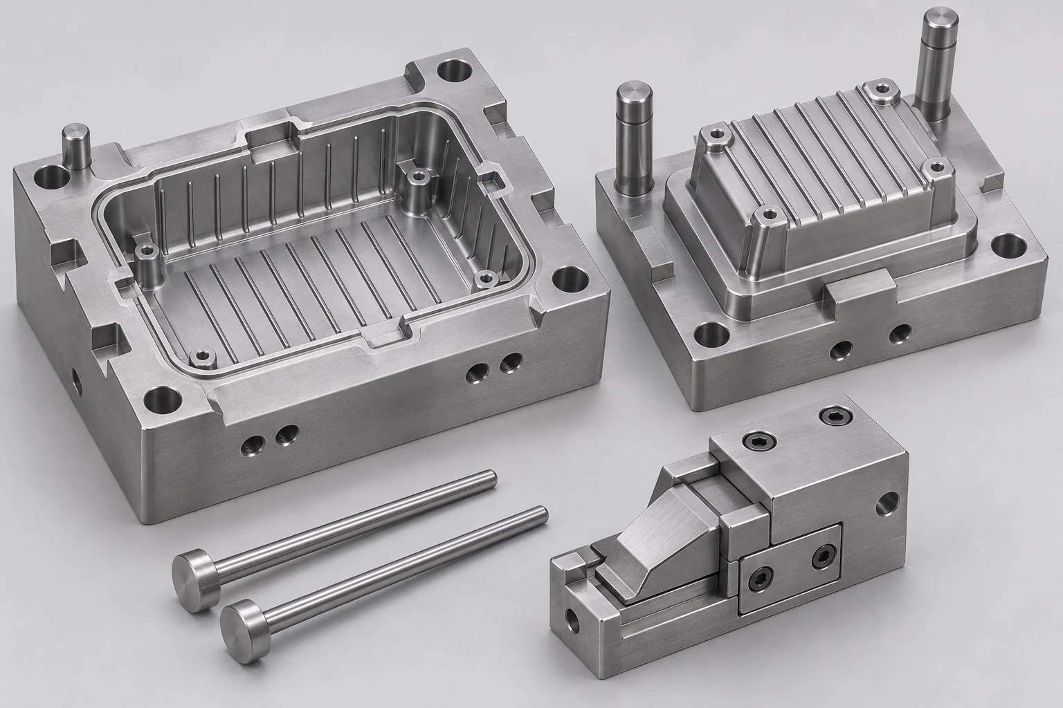
Illustrative die-casting mold with cavity, inserts and guide pillars
Die-cast tooling · concept illustration
Drawing-ledPart requirements come first
Aluminum & zincTooling matched to the alloy
Sample approvalChecks before production release
One project teamTooling through finished parts

Mold Development Around Your Part

The best tooling decisions start with the component, its application and the production plan. We review these details before cutting steel.

01 / Part & tool architecture

Make the important features
clear from the start.

Your casting needs to release from the tool, fill consistently and provide a practical starting point for machining and assembly.

  • Parting line & draftReview release direction, visible surfaces and the features that need side actions.
  • Gating, overflow & ventingPlan how the metal enters the cavity and where air can escape and overflows collect excess metal.
  • Machining allowance & datumsConnect the as-cast shape to the finished faces, holes and assembly interfaces.
Discuss your part design
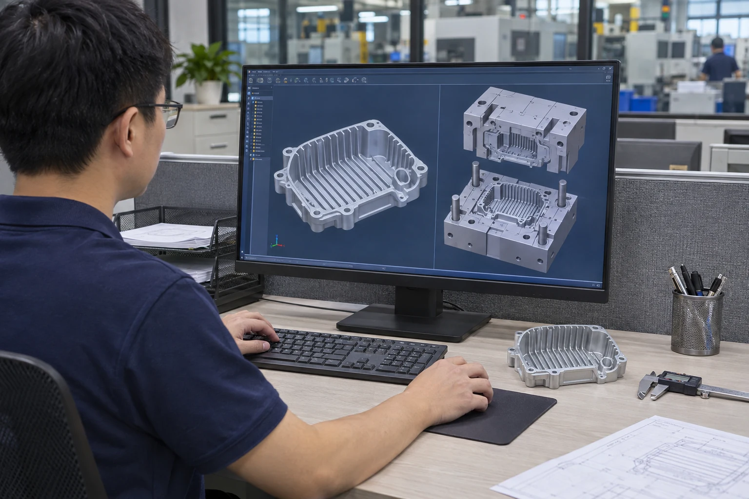
Illustrative engineering review of a die-cast part and tooling model
02 / Tool steel & inserts

Choose the construction
for the job ahead.

Alloy, part complexity, production volume and maintenance needs help define the tool construction. The specification is agreed for your project.

  • Cavity layoutReview part size, demand and the available casting route before confirming the layout.
  • Steel & heat treatmentSpecify the tool materials and treatment requirements for the selected alloy and duty.
  • Replaceable insertsConsider local wear, difficult features and access for future maintenance.
Review your tooling requirements
Illustrative tool-steel mold inserts with machined cavities
03 / Trial & production readiness

Approve the sample.
Confirm the next step.

A trial is the point to check the casting, review the tool and agree any adjustments before the production process is released.

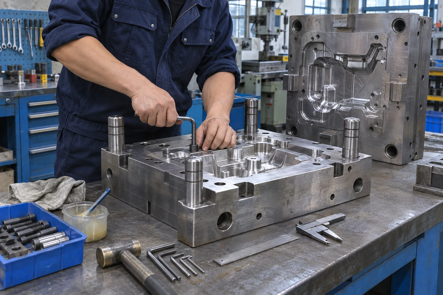
  • Tool assembly & fittingCheck the moving elements, insert fit and tool function before trial casting.
  • Sample reviewCompare the agreed dimensions, appearance and assembly features with the drawing.
  • Corrections & releaseDocument the agreed changes and confirm the approved reference for production.
See the development process
Illustrative fitting and assembly of a die-casting mold

Tooling illustrations throughout this page show representative processes and component types.

From Drawing to Approved Tooling

A clear sequence keeps design decisions, tool manufacture and sample approval connected.

  1. DFM drawing review illustration
    01

    DFM Review

    Confirm the alloy, geometry, critical features, finish and expected quantities.

  2. Die design illustration
    02

    Tool Design

    Develop the cavity, gating, cooling and ejection plan for the agreed route.

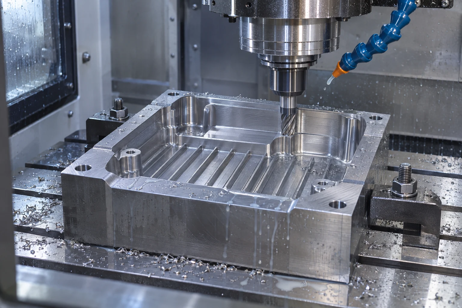
  3. CNC machining of a die-casting mold insert illustration
    03

    Tool Manufacture

    Machine the tool components, with EDM used where the detail requires it.

  4. Mold assembly and fitting illustration
    04

    Assembly & Fitting

    Bring the components together and check the tool’s mechanical function.

  5. Trial casting and sample review illustration
    05

    Trial & Correction

    Review trial castings and make the adjustments agreed for the part.

  6. Mold and sample dimensional inspection illustration
    06

    Sample Approval

    Confirm inspection results and the reference sample before release.

The Tooling Route Starts with the Application

Appearance, assembly and thermal requirements can lead to different tooling priorities.

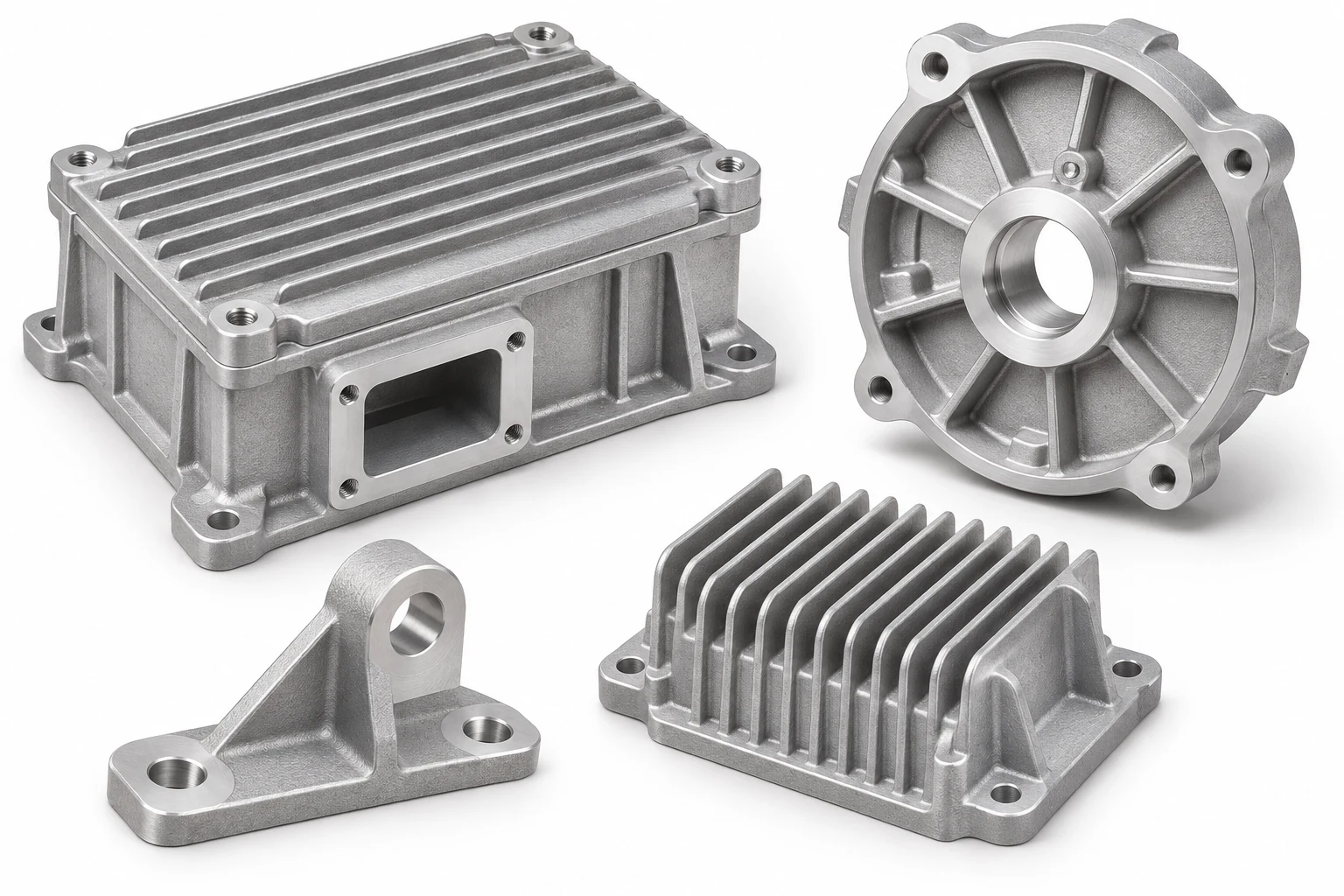
Illustrative aluminum die-cast housing and bracket samples

Housings, brackets and structural parts

Review wall transitions, ribs, bosses and machining stock together, so the tool produces a useful starting shape for the finished component.

  • Motor and electronics housings
  • Mounting brackets and supports
  • Parts with machined sealing or locating faces
Discuss an aluminum part

Control the Tool. Check the Part.

Inspection and maintenance are considered with the design, rather than left until the end.

Dimensions & Reference Features

Identify the tool features and sample dimensions that affect the finished component. Agree the measurement method and records required for approval.

  • Cavity and insert dimensions
  • Part datums and critical interfaces
  • Sample inspection requirements
Tool Function & Cavity Details

Review the areas that influence release, repeatability and visible part quality. Trial feedback helps identify practical corrections before production.

  • Parting surfaces and insert fit
  • Moving elements and ejection
  • Venting, cooling and local details
Maintenance & Tool Changes

Keep the tool condition and approved revision clear through production. Maintenance needs and any replacement inserts are reviewed for the specific tool.

  • Cleaning, wear review and condition checks
  • Insert replacement where appropriate
  • Changes recorded against the approved design
Illustrative dimensional inspection of a mold component
Dimensions and reference features · tooling illustration

What Your Tooling Project Needs

Practical DFM

Resolve draft, wall transitions, parting lines and machining needs while changes are still easier to make.

Clear Specifications

Keep the alloy, tool construction, sample criteria and project responsibilities in one agreed brief.

Connected Processes

Plan the tool with casting, CNC machining, surface finishing and final assembly in mind.

Controlled Approval

Use inspection results, trial feedback and the approved sample as the reference for the next stage.

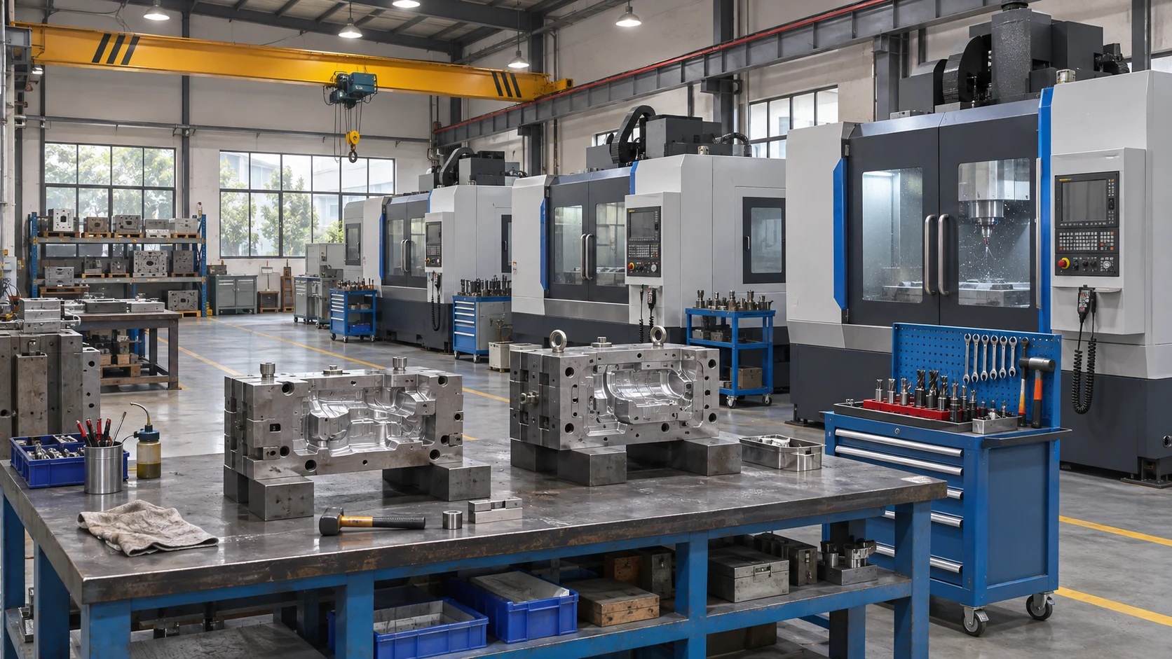
Illustrative organized mold-making toolroom with machining equipment
Toolroom workflow illustration

Tooling Through the Full Production Route

Develop the tool with
the next operation in mind.

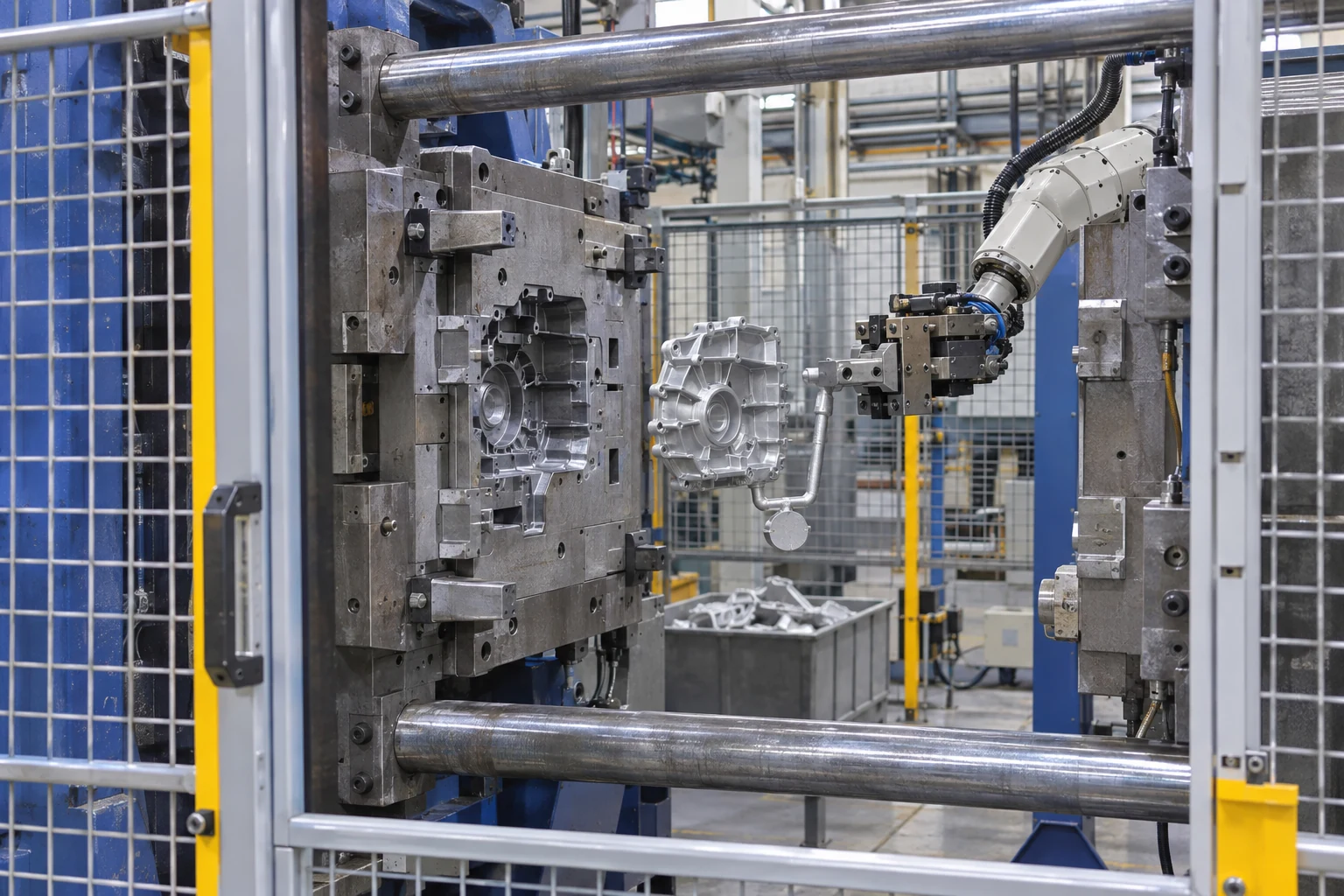
A part may leave the casting machine and still need trimming, machining, surface treatment and assembly. Those requirements belong in the tooling discussion from the start.

Review your production route

Start with a Clear Tooling Brief

A drawing is a good starting point. The information around it helps us review the right route and prepare a useful quotation.

What to Send

  • 3D model and dimensioned PDF drawing
  • Aluminum or zinc alloy, if selected
  • Sample quantity and expected production volume
  • Critical dimensions, visible areas and mating parts
  • Machining, finishing and inspection requirements
  • Target timing and any existing tool information
Before Tool Release

Agree the decisions
that affect the result.

Confirm the drawing revision, material, tool scope, trial plan and sample acceptance requirements. If a feature changes, review its effect on the tool and the finished component before work continues.

Discuss your project

Tooling Development FAQs

What affects tooling cost and lead time?

Part size, complexity, alloy, cavity layout, tool construction and sample requirements all matter. Send the model, drawing and expected volume so we can review the scope before confirming a quotation and schedule.

Can every dimension be produced directly by die casting?

Some interfaces need secondary machining. Identify the critical fits, sealing areas, threads and datum relationships on the finished-part drawing. We review what can be cast and where machining allowance is needed.

What is checked during sample approval?

The approval plan should cover the agreed dimensions, appearance, assembly features and any project-specific tests. Inspection results and trial feedback are reviewed together, and required corrections are agreed before release.

Can we change the design after the tool is made?

A change needs an engineering review. Some revisions can be handled by machining or replacing inserts; others may need more extensive work. Share the revised model and drawing so the effect on cost, timing and part quality can be assessed.

How are tool maintenance and replacement inserts handled?

The plan depends on the tool design, production conditions and wear. Maintenance requirements, tool condition and any replacement inserts should be recorded against the approved tooling revision.

Let’s Review
Your Tooling Project

Send your drawing and tell us what the part needs to do. MSdean will review the tooling route, sample requirements and quotation with you.

  • Part design and manufacturing review
  • Tool scope and sample approval planning
  • Machining, finishing and assembly requirements
  • One contact from tooling to finished parts
info@msdeanmfg.com

Tell us about your project

Start with the details you have.

Portfolio preview. This form is for demonstration only.

The details you provide will be used to respond to your project inquiry.

Discuss your project

Share your part drawing, material and expected quantity.

Portfolio preview. This form is for demonstration only.

The details you provide will be used to respond to your project inquiry.